Switching device for single-phase or multiphase electric consumer

A technology for switching devices and electrical consumers, applied in electrical switches, electronic switches, output power conversion devices, etc., can solve problems such as high production costs, heat loss effects, etc., to achieve compact and cost-effective, simple on or off , compact and structured effect

Pending Publication Date: 2020-09-08
SIEMENS AG
View PDF11 Cites 0 Cited by
  • Summary
  • Abstract
  • Description
  • Claims
  • Application Information

AI Technical Summary

Problems solved by technology

This wiring overhead can negatively affect the heat loss developed in operation
In any case, high production costs are associated with this due to costly manufacturing steps

Method used


Image

  • Switching device for single-phase or multiphase electric consumer
  • Switching device for single-phase or multiphase electric consumer
  • Switching device for single-phase or multiphase electric consumer

Examples


Embodiment Construction

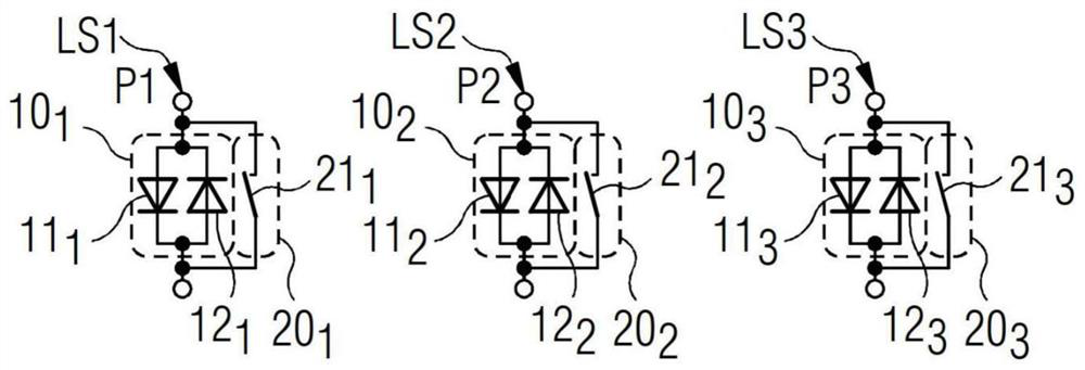
[0032] figure 1 A schematic diagram showing an equivalent circuit diagram of a switching device for a three-phase consumer. The switching device is described below on the basis of a soft starter, but this is not to be regarded as restrictive. Consumers represent, for example, working machines, in particular permanently excited three-phase electric machines. In the respective wiring harness LS1 , LS2 , LS3 of each phase P1 , P2 , P3 a switching module is arranged. Each switch module includes a power module 10 1 、10 2 or 10 3 and bridge unit 20 1 、20 2 or 20 3 . The subscripts "1", "2" or "3" following the reference numerals in the figures indicate the corresponding elements of the phases P1, P2 or P3.

[0033] In the corresponding switch module, the power module 10 1 、10 2 、10 3Comprising two controllable semiconductor switching elements 11 connected in antiparallel 1 and 12 1 、11 2 and 12 2 and 11 3 and 12 3 . with controllable semiconductor switching elemen...


PUM


Abstract

The invention relates to a switching device for a single-phase or multiphase electric consumer. A switching device includes a number of line sections corresponding to a number of phases, each including a first and a second connection part, for connection to a connection phase of an electrical consumer. At least one controllable semiconductor switching element is provided per phase, wired between the first and second connection part. A bypass unit includes one controllable electromechanical switching element with a low on-resistance per phase. The controllable electromechanical switching element is wired, in parallel with the controllable semiconductor switching element of this phase, between the first and second connection part. The first and second connection part of a respective phase are arranged adjacently on one side of the power module in spatial proximity in a direction of extent. A contact bridge, assigned to a respective phase, runs in the direction of extent in order to electrically connect the first and second connection part in the switched-on state.

Description

technical field [0001] The invention relates to a switching device for single-phase or multi-phase consumers. The switchgear includes a number of wire harnesses corresponding to the number of phases, wherein each wire harness includes a first connection portion serving as an input terminal for connecting with a power source, and serving as an output terminal for connecting with an electric consumer. The connected second connection part. The switchgear also includes power modules and bridge units. The power module comprises at least one controllable semiconductor switching element per phase, wherein the at least one controllable semiconductor switching element is connected between the first and the second connection part. The bridge unit comprises in each phase a controllable electromechanical switching element with a low on-resistance, wherein the controllable electromechanical switching element is connected in parallel with at least one controllable semiconductor switching ...

Claims


Application Information

Patent Timeline
Patent Type & Authority Applications(China)
IPC IPC(8): H02M1/00H02P1/02H02P1/16H01H1/58H05K7/06H05K7/20H01L23/467H01L23/40H01L23/367
CPCH02M1/00H02P1/02H02P1/16H01H1/58H05K7/06H05K7/20136H05K7/2039H05K7/209H05K7/20909H01L23/367H01L23/4006H01L23/467H02M1/36H02M5/257H02M7/003Y02B70/10H02M1/0048H02M1/327H05K7/14329H01H9/541H01H71/125H03K17/166H05K7/1432H05K7/20918
Inventor P.卡斯鲍尔J.恩格尔曼
Owner SIEMENS AG
Why Eureka
Try Eureka