An underwater natural gas pipeline leakage automatic sealing robot and its application method

A technology of natural gas pipelines and robots, which is applied in the direction of manipulators, pipe components, mechanical equipment, etc., can solve the problems of increasing operational difficulty, economic loss, and difficult operation, and achieve good protection effects

A technology of natural gas pipelines and robots, which is applied in the direction of manipulators, pipe components, mechanical equipment, etc., can solve the problems of increasing operational difficulty, economic loss, and difficult operation, and achieve good protection effects

CN111795253BActive Publication Date: 2022-01-18重庆创御智能装备有限公司

Image

  • An underwater natural gas pipeline leakage automatic sealing robot and its application method
  • An underwater natural gas pipeline leakage automatic sealing robot and its application method
  • An underwater natural gas pipeline leakage automatic sealing robot and its application method

Examples


Embodiment 1

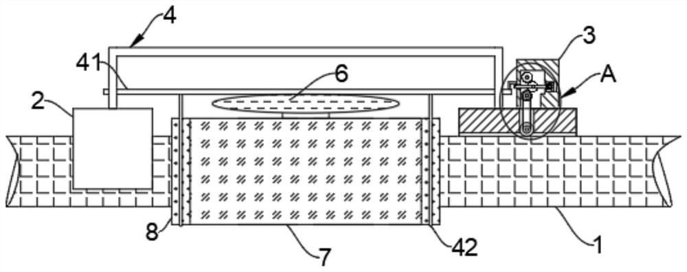
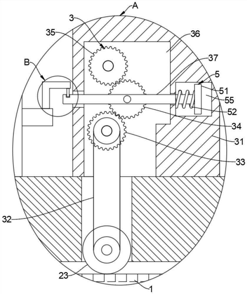
[0033] Such as Figure 1-5 As shown, an underwater natural gas pipeline leakage automatic sealing robot and its use method include a support mechanism 2 connected with a pipeline 1, such as Figure 4 As shown, the support mechanism 2 is composed of a fixed cylinder 21 , a fixed wheel 22 and a support wheel 23 .

[0034] The section of the fixing cylinder 21 is a 2 / 3 arc structure, and the fixing cylinder 21 has a three-section hinge structure, so that the fixing cylinder 21 can be conveniently fixed on the pipeline 1 .

[0035] The fixed wheel 22 is rotatably connected to both sides of the fixed cylinder 21 and is rollingly connected with the pipeline 1 along the axial direction of the pipeline 1. The supporting wheel 23 is located at the top of the pipeline 1 and is rollingly connected with the pipeline 1 along the axial direction of the pipeline 1. 21 turn to connect.

[0036] Both the support wheel 23 and the fixed wheel 22 can ensure that the support mechanism 2 can easily...

Embodiment 2

[0052] like Figure 6-7 As shown, the difference between this embodiment and Embodiment 1 is that: a vertical rack 43 is fixedly connected to the top of the support mechanism 2, the rack 43 is fixedly connected to the connecting piece 4, and the sliding rod 37 is rotatably connected to a rotating cylinder 44 , the rotating cylinder 44 is fixedly connected with a rotating gear 45 and a take-up wheel 46 , and the take-up wheel 46 is fixedly connected with the stay cord 42 .

[0053] And then realize that when the sliding bar 37 slides upwards, the rotating gear 45 cooperates with the tooth bar 43 and then can realize that the rotating gear 45 drives the rotating cylinder 44 to rotate, and then realizes that the rotating cylinder 44 drives the take-up pulley 46 fixedly connected therewith to rotate, and the take-up The wheel 46 has a larger diameter, and then it can be realized that when the sliding rod 37 slides a certain distance, the take-up wheel 46 will make the pulling dist...


PUM


Abstract

The invention belongs to the field of natural gas transportation, and in particular relates to an underwater natural gas pipeline leakage automatic sealing robot and its use method, which includes a support mechanism connected to the pipeline. There are two support mechanisms, one of which is the support mechanism A driving mechanism is provided on the top, and a connecting piece is fixedly connected between the two supporting mechanisms, and sliding rods are slidably connected at both ends of the connecting piece, and a limiting mechanism matching with the sliding rod is provided on the driving mechanism. The present invention can realize that when there is a pipeline leak in the device, the gas will pass through the support tube and enter the airbag to expand the airbag, and the expansion of the airbag will realize the sliding The rod moves upwards, and then the sliding rod pulls the pull rope, and the stretching will tighten the protective film so that the protective film is tightly attached to the outside of the pipe, and then the two ends of the leaking part of the pipe are blocked by the protective film, thereby realizing The air leakage of the pipeline is blocked in the support cylinder.

Description

technical field [0001] The invention belongs to the technical field of natural gas transportation, and in particular relates to an underwater natural gas pipeline leakage automatic sealing robot and a use method thereof. Background technique [0002] At present, most natural gas refers to a mixture of hydrocarbon and non-hydrocarbon gases naturally stored in the formation. Natural gas contains almost no sulfur, dust and other harmful substances. When burned, it produces less carbon dioxide than other fossil fuels, resulting in a lower greenhouse effect. , so it is a relatively clean energy. Most of the natural gas is transported by pipelines, and a few are transported by tankers. For offshore gas fields, it is more efficient to transport the collected natural gas through underwater pipelines. [0003] However, the transportation of underwater pipelines may cause damage to the pipeline due to the attachment of shellfish to the surface of the pipeline, and because the pipeline...

Claims


Application Information

Patent Timeline
18 Jan 2022
Publication
CN111795253B
IPC
F16L55/17; F16L55/18; B25J11/00
CPC
F16L55/17; F16L55/18; B25J11/00
Inventors
高奎武