
Equipment and method for detecting and repairing defective shaft parts

A shaft parts, bad technology, applied in the field of mechanical parts processing, can solve the problems that the grooves and cracks on the surface of shaft parts cannot be fully filled, the flexibility and practicability of the device need to be improved, and the defects of the catalytic liquid cannot be tightly fitted, etc. , to achieve the effect of improving practicability and flexibility, improving restoration quality, and reducing detection steps

Active Publication Date: 2021-08-10
山东聊城中泰表业有限公司
View PDF14 Cites 0 Cited by
  • Summary
  • Abstract
  • Description
  • Claims
  • Application Information

AI Technical Summary

Problems solved by technology

[0006] 1. It is impossible to implement corresponding repair methods for the surface defects of shaft parts, so the flexibility and practicability of the device need to be improved
[0007] 2. Although the alloy catalytic liquid has the effect of recycling, its repair method is to directly inject the catalytic liquid into the outer surface of the shaft parts. The catalytic liquid is liquid and has strong fluidity. Using this repair method, the shaft cannot be repaired. The grooves and cracks on the surface of the parts are fully filled, that is, the catalytic fluid and the defects on the surface of the shaft parts cannot be tightly bonded, so the repair quality needs to be improved
[0008] 3. When testing the quality of shaft parts, it needs to be debugged in advance. At the same time, there are many detection steps, complicated operations, and a lot of time wasted, thus reducing the detection efficiency of shaft parts

Method used


Image

  • Equipment and method for detecting and repairing defective shaft parts
  • Equipment and method for detecting and repairing defective shaft parts
  • Equipment and method for detecting and repairing defective shaft parts

Examples


Embodiment Construction

[0050] The technical solutions of the present invention will be further described below in conjunction with the accompanying drawings and through specific implementation methods.

[0051] Wherein, the accompanying drawings are only for illustrative purposes, showing only schematic diagrams, rather than physical drawings, and should not be construed as limitations on this patent; in order to better illustrate the embodiments of the present invention, some parts of the accompanying drawings will be omitted, Enlarged or reduced, does not represent actual product size.

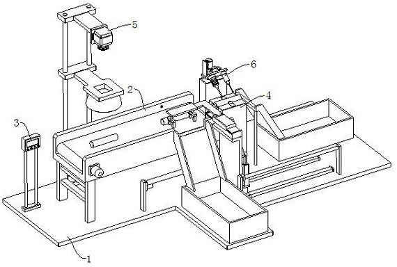
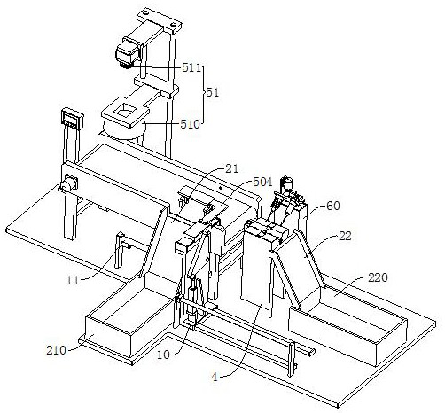
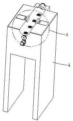
[0052] refer to Figure 1 to Figure 10 The shown equipment for detecting and repairing defective shaft parts includes a base 1 and a conveyor belt 2, the conveyor belt 2 is set on the top of the base 1, and also includes a controller 3, a processing table 4, a screening mechanism 5 and a repairing Mechanism 6, the controller 3 is set on the top of the base 1, the processing table 4 is set on the top of the base 1...


PUM


Abstract

The present invention relates to the field of mechanical parts processing, in particular to an equipment and method for detecting and repairing defective shaft parts, including a base and a conveyor belt, the conveyor belt is set on the top of the base, and also includes a controller, a processing table, and a screening mechanism and the repair mechanism, the processing table is set on the top of the base to place shaft parts, the screening mechanism is set on the top of the base to detect shaft parts, the screening mechanism includes a retrieving component and an image recognition component, and the repair The mechanism is set on the top of the base to repair the shaft parts. The repair mechanism includes a column, a spraying assembly and a grinding assembly. The conveyor belt, the picking assembly, the image recognition assembly, the spraying assembly, the grinding assembly and the controller are all electrical. Connection, the invention relates to an equipment and method for detecting and repairing defective shaft parts, which can repair different damages, and can repair the damage perfectly at the same time, with high repair quality and high detection efficiency, which is convenient to shorten the repair process and improve the overall repair efficiency .

Description

technical field [0001] The invention relates to the field of machining of mechanical parts, in particular to an equipment and method for detecting and repairing defective shaft parts. Background technique [0002] In the field of machinery manufacturing, the manufacturing and processing of shaft parts are often involved, and shaft parts play a vital role in the operation of mechanical equipment. With the development of mechanical equipment manufacturing technology, the machining accuracy of mechanical parts has been continuously improved, and correspondingly higher requirements have been put forward for measurement technology. At present, the detection of size and shape error of shaft parts in China usually adopts manual detection method, and different detection tools need to be applied according to different detection requirements, the detection efficiency is not high and the detection accuracy cannot be guaranteed. [0003] my country's patent application number: CN201910...

Claims


Application Information

Patent Timeline
Patent Type & Authority Patents(China)
IPC IPC(8): B24B5/36B24B5/35B24B41/02B24B51/00B24B47/04B24B47/14B24B47/22B07C5/34B07C5/36B05B16/20B05B7/16B23P6/00
CPCB05B7/1606B05B7/166B07C5/34B07C5/362B23P6/00B24B5/35B24B5/36B24B41/02B24B47/04B24B47/14B24B47/22B24B51/00B05B16/20
Inventor 徐玉芝洪思宜
Owner 山东聊城中泰表业有限公司
Learn More