Medical drainage control device

A technology of a control device and a drainage bag, which can be used in suction devices, other medical devices, hypodermic injection devices, etc., can solve the problems of increasing the burden on medical staff and patients' families, failing to follow the doctor's expectation, and ensuring the drainage effect is difficult to achieve. Improve safety and stability, ensure drainage effect, and reduce workload

Inactive Publication Date: 2020-11-17
德州飚丰信息技术有限公司
View PDF0 Cites 0 Cited by
  • Summary
  • Abstract
  • Description
  • Claims
  • Application Information

AI Technical Summary

Problems solved by technology

[0004] In the clinical operation of drainage of a large amount of effusion, there are often specific requirements for clinical parameters such as daily drainage times, each drainage volume, and drainage speed according to the condition of the case. The parameters are usually controlled subjectively by the medical staff or the patient's family members. The current artificial control method has certain disadvantages. As a result, the drainage process cannot be carried out in the way the doctor expected, and the improper drainage will cause discomfort and injury to the patient, and even endanger the patient's life. On the other hand, the real-time drainage volume and drainage speed during the drainage process are usually determined by human observation. Judgment, the error is large, and it is difficult to guarantee the drainage effect. At the same time, the current control method will obviously increase the burden on the medical staff and the patient's family members.
[0005] The drainage bag is a relatively cheap medical product, and it is the best choice as the terminal container in clinical effusion drainage, but it can only be applied to conventional pleural effusion drainage operations under normal pressure, and cannot be applied to negative pressure drainage. Negative pressure drainage usually requires the use of water-sealed bottles that are more expensive than drainage bags, which brings a certain economic burden to patients

Method used


Image

  • Medical drainage control device
  • Medical drainage control device
  • Medical drainage control device

Examples


Embodiment 1

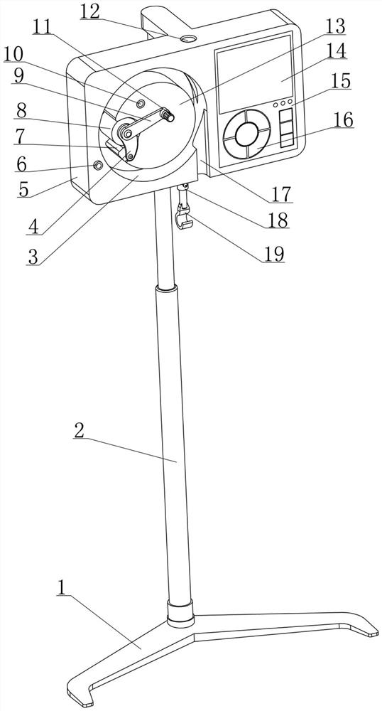
[0040] see figure 1 , 2 As shown, a medical drainage control device disclosed in this embodiment is composed of a bracket assembly, a weighted suspension assembly 18, a drainage adjustment assembly, a controller 15 and a power supply part 20;

[0041] Among them, see figure 1 , 2 As shown, the bracket assembly is composed of a base 1, a column 2 and a mounting plate 5. The column 2 is supported by the base 1 and extends vertically. Front side; the placement plate 5 is used to provide support and installation space for other components;

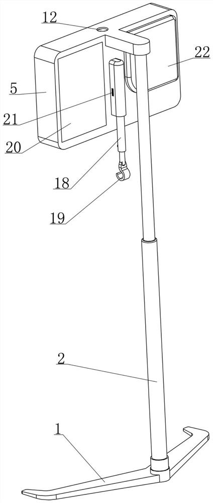
[0042] Among them, see figure 2 , 8 , 9, the weight-based suspension assembly 18 is supported by the placement plate 5, and has a built-in load cell 21, and the lower end is provided with a suspension part 19 for connecting the drainage bag 25; it can provide the only drainage bag 25. Support and make the drainage bag 25 hang below the placement plate 5, which can adjust the height of the drainage bag 25, and the load cell 21 outputs a ...

Embodiment 2

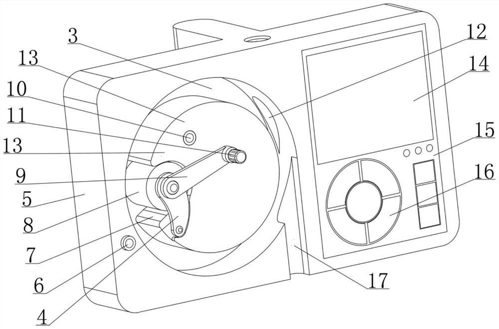
[0083] see image 3 , 4 As shown, in the medical drainage control device disclosed in the foregoing embodiments, the introduction hole 12 is set inside the placement plate 5 and its cross section is circular, so as to ensure the integrity of the side wall of the recess 3 to the greatest extent. Based on the introduction hole 12 With the circular hole structure adopted, when the drainage tube 23 is introduced into the annular gap, it is necessary to pass the tail end of the drainage tube 23 through the introduction hole 12 from front to back, and the operation is not convenient enough; On the basis of , the installation board 5 has the following improvements:

[0084] see Figure 12 , 13 As shown, the set plate 5 has a square groove 39 that can fully expose the introduction hole 12 on the front side wall, and a sliding baffle 18 with a moving stroke is defined in the square groove 39; when the sliding baffle 18 is in its stroke At the beginning, it will block the front side...

Embodiment 3

[0087] see Figure 8 As shown, in the medical drainage control device disclosed in Embodiment 1, the accuracy of the weighing signal output by the load cell 21 is greatly affected by whether the medical drainage control device is placed horizontally, and the specific reasons have been clarified; When it is poor, it can be solved by laying objects under the base 1, but the operation is more troublesome, time-consuming and labor-intensive. Therefore, this embodiment is based on the structure of the medical drainage control device disclosed in embodiment 1. Also has the following improvements:

[0088] see Figure 14 , 15As shown, the rear side of the placement plate 5 is fixed with a first rotating shaft 42 extending horizontally backward, and a swing seat 43 is fixed by the first rotating shaft 42 to swing left and right in a small range; The upper end is connected with the swing seat 43 through the second rotating shaft 41 so that the weight-based suspension assembly 18 can...


PUM


Abstract

The invention relates to the field of medical instruments, and discloses a medical drainage control device. The medical drainage control device is composed of a support assembly, a weighing type suspension support assembly supported by the support assembly, and a drainage adjusting assembly, a controller and a power supply part. The weighing type suspension support assembly can provide support fora drainage bag and feed back a weight signal reflecting the weight change state of an effusion to the controller. The drainage adjusting assembly can extrude a drainage tube in different modes to adjust the drainage state. The controller can adjust and control the working state of the drainage adjusting assembly based on the obtained weight signal, a preset drainage mode and a preset drainage parameter. The medical drainage control device adopts an intelligent design, can realize automatic control of timing drainage, quantitative drainage and constant-speed drainage by being matched with an existing conventional drainage assembly for use, improves the safety and stability of drainage operation, has two drainage modes of normal-pressure drainage and negative-pressure drainage, can meet most clinical drainage requirements, and is wide in clinical application prospects.

Description

[0001] The present invention is a divisional application of the invention patent application with application number 2018111350191 submitted on September 28, 2018. technical field [0002] The invention relates to the technical field of medical devices, in particular to a medical drainage control device capable of controlling the drainage state in clinical drainage. Background technique [0003] Under normal conditions, there is a small amount of fluid in the thoracic cavity and abdominal cavity of the human body, which can lubricate the organs in the cavity. If the amount of fluid in the cavity increases beyond the normal physiological range under pathological conditions, it will become a disease, such as pleural effusion and ascites. There are many causes of peritoneal effusion and pleural effusion, which are very common clinical diseases. Although peritoneal effusion and pleural effusion are only one symptom, a large amount of peritoneal effusion and large amount of perit...

Claims


Application Information

Patent Timeline
Patent Type & Authority Applications(China)
IPC IPC(8): A61M1/00
CPCA61M1/0023A61M2205/3334A61M1/74
Inventor 王才丰
Owner 德州飚丰信息技术有限公司
Why Eureka
Try Eureka