Shell-less low-intermodulation device for network communication

A network communication and channel technology, applied in the field of communication equipment, can solve the problems of wasting staff time, inconvenient maintenance and replacement, and unfavorable use, and achieve the effects of preventing malicious damage, facilitating disassembly and maintenance, and prolonging service life.

Pending Publication Date: 2020-11-27
湖南德信智创智能科技有限公司
View PDF0 Cites 0 Cited by
  • Summary
  • Abstract
  • Description
  • Claims
  • Application Information

AI Technical Summary

Problems solved by technology

[0002] Communication equipment is wired communication equipment and wireless communication equipment used in industrial control environments. Wired communication equipment mainly introduces solutions to industrial site serial communication, professional bus communication, industrial Ethernet communication and conversion equipment between various communication protocols. Wireless communication equipment is mainly wireless AP, wireless network bridge, wireless network card, wireless lightning arrester, antenna and other equipment. The existing shellless low intermodulation device for network communication has the problem that it is not easy to maintain and replace. Because the shellless low intermodulation device for network communication The intermodulation device is usually fixed somewhere with bolts. When replacing and maintaining the shellless low intermodulation device for network communication, it is necessary to remove all the bolts to move the shellless low intermodulation device for network communication. Trouble, wasting a lot of staff time, not conducive to use

Method used


Image

  • Shell-less low-intermodulation device for network communication
  • Shell-less low-intermodulation device for network communication
  • Shell-less low-intermodulation device for network communication

Examples


Embodiment 1

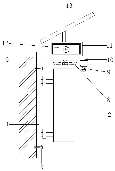
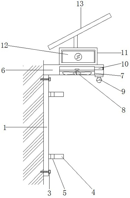
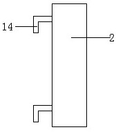
[0019] Embodiment 1, with reference to Figure 1-3 , a shellless low intermodulation device for network communication, including a mounting plate 1 and a low intermodulation device body 2 fixed on the wall by bolts 3, two ends of the outer wall of the mounting plate 1 away from the wall are welded The fixed plate 4 has a fixed opening 5 on the top of the fixed plate 4, the top plate 6 is welded on the top of the installed plate 1, and the outer wall of the bottom of the top plate 6 is provided with a mounting groove 7, which can be realized by clamping the L-shaped plate on the fixed plate 4. The quick installation of the low intermodulation device body 2 is very convenient for the disassembly and maintenance of the intermodulation device body 2 later, which greatly improves the work efficiency and reduces the work intensity;

[0020] An electric fan 8 is installed by a fixed rod in the installation groove 7, and the air blowing direction of the electric fan 8 is to blow downw...


PUM


Abstract

The invention discloses a shell-less low intermodulation device for network communication. The low-intermodulation device comprises a mounting plate and a low-intermodulation device body which are fixed on a wall surface through bolts. Two fixing plates are welded to the two ends of the outer wall of the side, away from the wall, of the mounting plate. A fixing opening is formed in the top of thefixing plate. A top plate is welded at the top of the mounting plate. A mounting groove is formed in the bottom outer wall of the top plate. An electric fan is installed in the installation groove through a fixing rod, a camera is installed at the end, away from the mounting plate, of the outer wall of the bottom of the top plate, a channel is formed in the outer wall of the side, away from the installation plate, of the top plate, a battery box is installed at the top of the top plate, a storage battery is arranged in the battery box, and a solar cell panel is installed at the top of the topplate. According to the invention, the L-shaped plate can be clamped on the fixed plate, so that the low-intermodulation device body can be quickly mounted, the intermodulation device body can be dismounted and maintained very conveniently in the later period, the working efficiency is greatly improved, and the working intensity is reduced.

Description

technical field [0001] The invention relates to the technical field of communication equipment, in particular to a caseless low intermodulation device for network communication. Background technique [0002] Communication equipment is wired communication equipment and wireless communication equipment used in industrial control environments. Wired communication equipment mainly introduces solutions to industrial site serial communication, professional bus communication, industrial Ethernet communication and conversion equipment between various communication protocols. Wireless communication equipment is mainly wireless AP, wireless network bridge, wireless network card, wireless lightning arrester, antenna and other equipment. The existing shellless low intermodulation device for network communication has the problem that it is not easy to maintain and replace. Because the shellless low intermodulation device for network communication The intermodulation device is usually fix...

Claims


Application Information

Patent Timeline
Patent Type & Authority Applications(China)
IPC IPC(8): H05K5/02H05K7/14H05K7/20H02J7/00H02J7/35
CPCH02J7/0045H02J7/35H05K5/0217H05K5/0247H05K7/14H05K7/20136
Inventor 吴翔
Owner 湖南德信智创智能科技有限公司
Why Eureka
Try Eureka