a centrifuge

A centrifuge and centrifuge mechanism technology, applied in the field of centrifuges, can solve the problems of hazardous operation and trouble for medical staff, and achieve the effect of shortening the operation time and reducing the workload.

Active Publication Date: 2022-05-27
THE SECOND AFFILIATED HOSPITAL ARMY MEDICAL UNIV
View PDF6 Cites 0 Cited by
  • Summary
  • Abstract
  • Description
  • Claims
  • Application Information

AI Technical Summary

Problems solved by technology

[0004] The present invention intends to provide a centrifuge to solve the problem in the prior art that the aerosol that exists after the specimen in the test tube is uncapped brings harm to the medical staff and the specimen in the test tube is moved after being centrifuged and then uncapped Troublesome operating problems

Method used


Image

  • a centrifuge
  • a centrifuge
  • a centrifuge

Examples


Embodiment 1

[0040] Embodiment one is basically as attached Figure 1 to Figure 9 Shown:

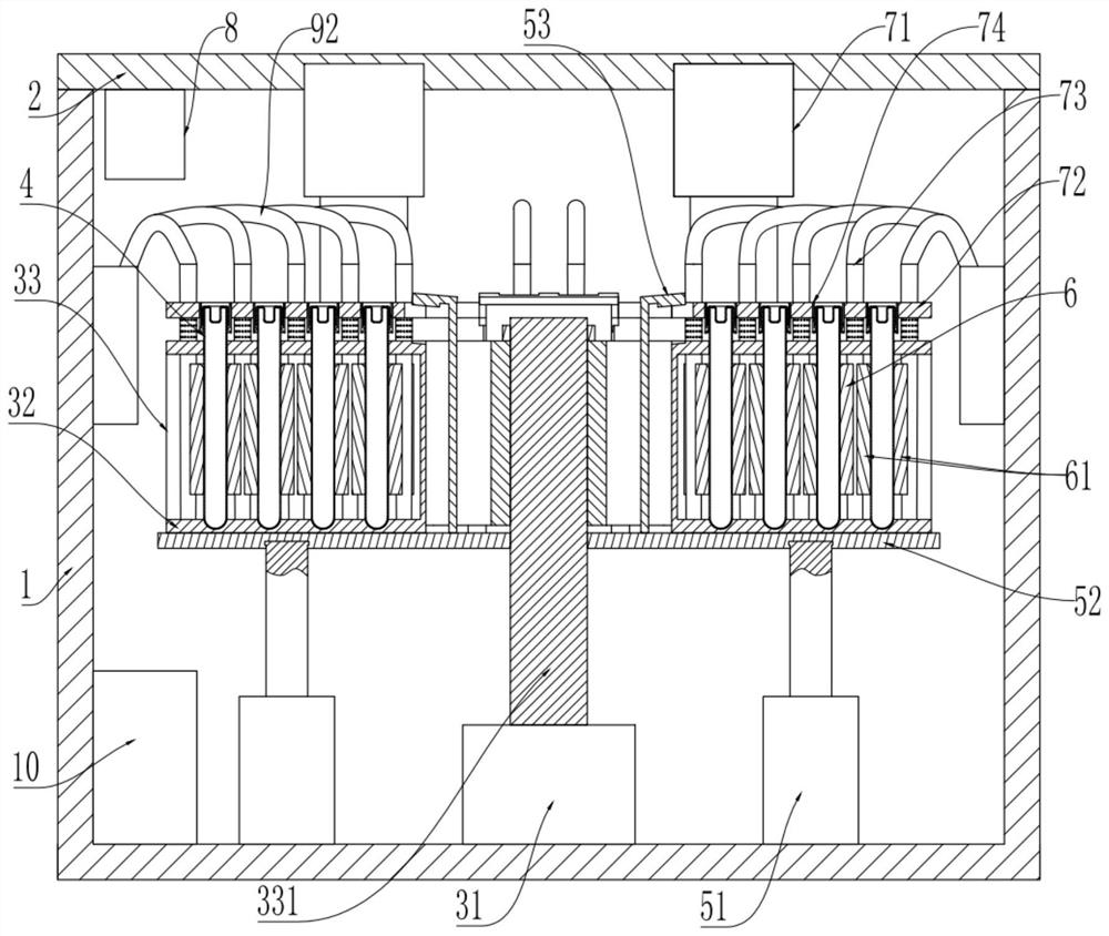
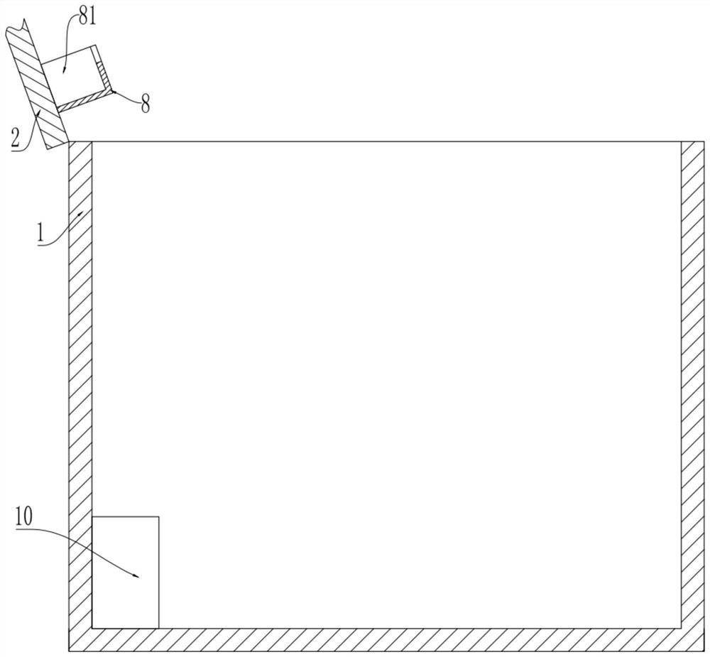
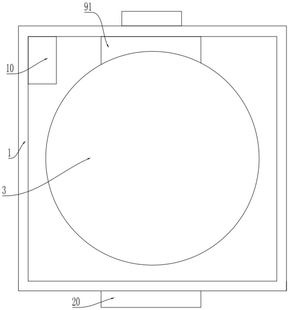
[0041] combine Figure 1 to Figure 4, a centrifuge, including a housing 1, a cover 2, a centrifugal mechanism 3 located in the housing 1, a holding mechanism, a cover opening mechanism and a negative pressure mechanism 91, the cover 2 forms a closed after the housing 1 is closed Space, the cover body 2 is rotatably connected to the casing 1, the cover body 2 covers the casing 1, the centrifugal mechanism 3 includes a first driver 31, a placement frame 32 and a turntable 33, and the first driver 31 is fixedly connected to the bottom of the casing 1 , the first driver 31 adopts a servo motor, the bottom of the turntable 33 is integrally formed with a vertical shaft 331, the shaft 331 is fixedly connected to the first driver 31, the first driver 31 drives the turntable 33 to rotate, and the placement frame 32 is connected to the turntable 33 in rotation, The placement racks 32 are evenly distributed i...

Embodiment 2

[0058] Embodiment two is basically as attached Figure 10 As shown, embodiment two has carried out following improvement on the basis of embodiment one: between negative pressure machine 91 and negative pressure pipe 92, also be fixedly connected with disinfection tube 30, photocatalyst filter screen 40 and ultraviolet disinfection are installed in the disinfection tube 30 The lamp 50 and the photocatalyst filter screen 40 are V-shaped.

[0059] The specific implementation process is as follows:

[0060] After the negative pressure machine 91 sucks the aerosol out of the housing 1 through the negative pressure tube 92, the aerosol first enters the disinfection tube 30, and the photocatalyst filter screen 40 and the ultraviolet disinfection lamp in the disinfection tube 30 realize air purification. The disinfection and sterilization of the sol ensures the cleanliness of the gas discharged through the negative pressure machine 91.


PUM


Abstract

The invention relates to the technical field of medical devices, and specifically discloses a centrifuge. The centrifugal mechanism includes a placement frame and a turntable. The placement frame is provided with test tube holes for placing test tubes. The placement frame is connected to the turntable. Each clamping group includes a clamping block symmetrically arranged along the test tube hole, and the clamping block is slidably connected to the placement frame; it also includes an uncapping mechanism and a negative pressure mechanism. The uncapping mechanism includes a lifter and an uncapping plate. The lifter drives the cap-opening plate to lift up and down. A guide rod is fixedly connected to the cap-opening plate. A cap-opener is also connected to the cap-opening plate. The guide rod can push the clamping block to move to clamp the test tube. The cap-opener is used to cover the test tube. Open; the negative pressure mechanism generates negative pressure to suck away the aerosol after the test tube is opened. This solution is used to solve the problem in the prior art that the aerosol that exists after opening the cap of the specimen in the test tube brings harm to the medical staff and the problem of troublesome operation in opening the cap after the specimen in the test tube is centrifuged and moved.

Description

technical field [0001] The invention relates to the technical field of medical instruments, in particular to a centrifuge. Background technique [0002] At present, almost all specimens in medical clinical testing are separated by centrifugation, and particles with low density are even centrifuged in a high-speed centrifuge. The centrifugation time is about 15 minutes to 30 minutes. Under the centrifugal rotation, a large number of bioactive particles contained in the specimen Aerosols such as viruses or viruses are separated from the specimens into a suspended state. When the specimens are opened (the specimens are usually packed in test tubes and centrifuged), the suspended bioactive particles or viruses will quickly float into the air, which is harmful to the staff and The environment causes great pollution, especially very small toxic or biologically active particles (below pm2.5) directly enter the respiratory tract, causing respiratory tract infection, and even enterin...

Claims


Application Information

Patent Timeline
Patent Type & Authority Patents(China)
IPC IPC(8): B04B5/04B04B7/00B04B7/02B04B15/00B04B15/08A61L9/20
CPCB04B5/0421B04B5/0442B04B7/00B04B7/02B04B15/00B04B15/08A61L9/205B04B2007/025B04B2007/005
Inventor 杜春兰杨国骏刘萍张立群
Owner THE SECOND AFFILIATED HOSPITAL ARMY MEDICAL UNIV
Why Eureka
Try Eureka