Self-resetting single-valve main and auxiliary piston hydraulic driving device and method for push rod engine

A driving device and self-resetting technology, applied in the direction of engine components, machines/engines, valve devices, etc., can solve the problems of system complexity, reduced reliability, and difficulty in arranging the hydraulic driving device of the engine, so as to simplify the overall installation structure and structure. compact effect

Active Publication Date: 2021-01-05
JIANSU JOINTEK PRECISION MASCH CO LTD
View PDF12 Cites 6 Cited by
  • Summary
  • Abstract
  • Description
  • Claims
  • Application Information

AI Technical Summary

Problems solved by technology

[0005] The technical problem to be solved by the present invention is: in order to overcome the fact that the existing engine valve mechanism has a compact structure, it is difficult to arrange the engine hydraulic drive device, and the engine drive function and the valve clearance automatic adju...

Method used


Image

  • Self-resetting single-valve main and auxiliary piston hydraulic driving device and method for push rod engine
  • Self-resetting single-valve main and auxiliary piston hydraulic driving device and method for push rod engine
  • Self-resetting single-valve main and auxiliary piston hydraulic driving device and method for push rod engine

Examples


Embodiment 1

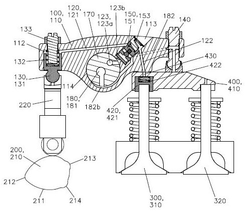
[0092] Such as Figure 1-10 The hydraulic drive device for a self-resetting single-valve main and auxiliary piston for a push rod engine shown includes a rocker arm assembly 100, an integrated cam and push rod assembly 200, an exhaust valve group 300, a valve bridge assembly 400 and a limit assembly 500, The rocker arm assembly 100 includes a rocker arm shaft 170, a rocker arm body 110 and a drive oil circuit 120, the rocker arm shaft 170 is arranged in the rocker arm shaft hole 114, the rocker arm body 110 is rotatably mounted on the rocker arm shaft 170, and the rocker arm body 110 One end is provided with driving main piston 130, and the other end is provided with first elephant foot assembly 140, and driving main piston 130 comprises main piston body 131, and one end of rocking arm body 110 is provided with main piston hole 112, and main piston hole 112 is connected with main piston. The oil passage 121 communicates, and the main piston body 131 is coaxially and slidably a...

Embodiment 2

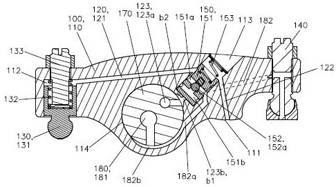
[0113] Such as Figure 11 Compared with Embodiment 1, the illustrated embodiment 2 differs only in that the auxiliary piston oil passage 122 communicates with the first elephant foot assembly 140, and the valve bridge body 410 is provided with an inner connection passage 411, and the first elephant foot assembly 140 communicates with the driving auxiliary piston 420 through the inner connecting channel 411 , and when the limiting surface 111 is set in contact with the valve bridge body 410 , the limiting surface 111 seals the oil drain channel 430 .

[0114] When the auxiliary piston oil passage 122 passes through the first elephant foot assembly 140, the lubricating oil passage 180 includes a rocker shaft lubricating oil passage 181 and a spray lubricating oil passage 183, and the rocker shaft lubricating oil passage 181 is opened on the rocker shaft 170 , the spray lubricating oil passage 183 is opened on the rocker arm body 110, which includes a spray lubricating section 183a...

Embodiment 3

[0116] In order to reduce the height of the rocker arm assembly 100 on the side of the integrated cam and push rod assembly 200, as Figure 12 Compared with Embodiment 1, the illustrated embodiment 3 differs only in that: the auxiliary piston oil passage 122 is communicated with a second elephant foot assembly 160, and the second elephant foot assembly 160 is arranged on the rocker arm body 110, and Located directly above the oil drain passage 430, the second elephant foot assembly 160 can be threaded or fixedly arranged on the rocker arm body 110 in the present invention. When the lower end of the second elephant foot assembly 160 contacts the valve bridge body 410, the second elephant foot assembly 160 Two elephant foot assemblies 160 are communicated with the oil drain passage 430, and the second elephant foot assembly 160 used in the present embodiment is an existing rocking arm elephant foot.


PUM


Abstract

The invention relates to a self-resetting single-valve main and auxiliary piston hydraulic driving device and method for a push rod engine. The self-resetting single-valve main and auxiliary piston hydraulic driving method comprises the steps that a rocker arm body and a valve bridge body are correspondingly provided with a driving main piston and a driving auxiliary piston, the driving auxiliarypiston is connected with an exhaust valve, and a driving oil path communicates with the driving main piston, the driving auxiliary piston and a driving control valve; when the driving control valve opens the drive oil path, the driving main piston and the driving auxiliary piston achieve hydraulic linkage, the rocker arm body and the valve bridge do not move during lift driving, and the driving auxiliary piston opens the exhaust valve; when the main lift starts, a main piston body oil path and an auxiliary piston oil path are disconnected, and the driving auxiliary piston resets automatically;and when the driving oil path is disconnected, in the integrated cam driving lift process, the driving main piston absorbs the driving lift of an integrated cam and a push rod assembly to the rockerarm body, the rocker arm body does not move, and the integrated cam driving lift is not transmitted to one side of the exhaust valve. The self-resetting single-valve main and auxiliary piston hydraulic driving method is simple in principle, compact in structure and easy to optimize, and the reliability and durability of engine driving operation are improved.

Description

technical field [0001] The invention relates to the technical field of side cam engines, in particular to a hydraulic drive device and method for a self-resetting single-valve main and auxiliary piston for a push rod engine. Background technique [0002] The concept and operation of compression release engine brakes is well known in the heavy commercial vehicle industry. Cost, power, reliability and engine change requirements are often factors in determining whether engine braking will be employed. Several different types of compression-release engine brakes exist in practical applications, among which the valve train integrated engine brake system has become more popular due to its low cost, high performance and reliability, and compact structure. [0003] One approach to engine braking system integration is to incorporate actuated valve lift into positive power cams and include "loose" devices in the valvetrain to hide or inhibit the braking lift of the valves from actuat...

Claims


Application Information

Patent Timeline
IPC IPC(8): F01L1/18F01L1/24F01L1/344F01L1/46
CPCF01L1/183F01L1/2422F01L1/3442F01L1/46F01L2001/34426
Inventor 崔立澜
Owner JIANSU JOINTEK PRECISION MASCH CO LTD
Why Eureka
Try Eureka