Grinding equipment with angle adjusting function

An angle adjustment and functional technology, applied in grinding/polishing equipment, grinding frame, grinding bed, etc., can solve problems such as complicated operation, high technical level requirements of operators, and high labor intensity of operators, and achieve Improve practicality, reduce labor intensity and improve work efficiency

Active Publication Date: 2021-02-26
CRRC QINGDAO SIFANG CO LTD
View PDF13 Cites 4 Cited by
  • Summary
  • Abstract
  • Description
  • Claims
  • Application Information

AI Technical Summary

Problems solved by technology

At present, the milling equipment has generally adopted automatic control, but the grinding tools often require the operator to hold the pneumatic grinding tool to operate. Due to the large surface area of ​​each block component, the range that needs to be finely ground is large, and sometimes it is caused by the shaking of the operator's hand. The flatness after fine grinding cannot meet the production requirements, the operator has high technical requirements, the operation is complicated, the processing quality cannot be guaranteed, and the labor intensity of the operator is high
[0004] At present, abrasive tools generally use angle grinders equipped with thousands of blades. Angle grinders use high-speed rotating sheet grinding wheels, rubber grinding wheels, steel wire wheels, etc. to grind, cut, derust, and polish metal components. The operator holds the angle grinder for operation
For example, a hand-push grinding tool for the roof of a motor vehicle disclosed in a Chinese patent includes a frame assembly, casters, a fixed frame assembly and an angle grinder assembly. The front end of the frame assembly is provided with casters, and the rear of the frame assembly is provided with a hand There is a switch connected to the angle grinder assembly under the handle, the angle grinder assembly is set at the front of the frame assembly through the fixing frame assembly, and the grinding angle of the angle grinder is adjusted through the adjustment lever. When in use, turn on the switch on the side of the handle, and the angle grinder assembly moves to realize the grinding process. Manually hold the handle to grind at the position that needs to be polished on the roof of the motor car, but the adjustable angle range of the angle grinder is limited, which cannot make the operation work in better posture

Method used


Image

  • Grinding equipment with angle adjusting function
  • Grinding equipment with angle adjusting function
  • Grinding equipment with angle adjusting function

Examples


Embodiment 1

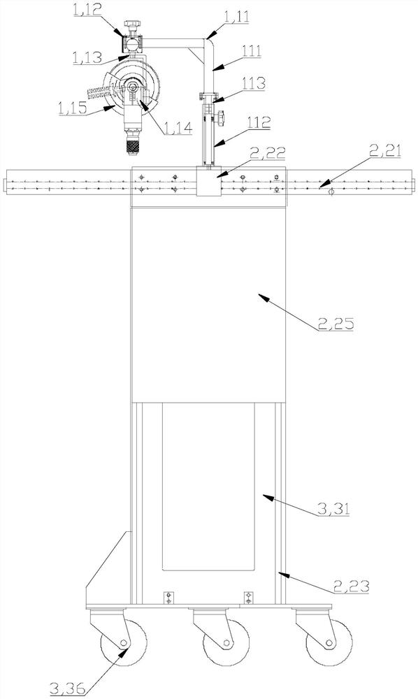
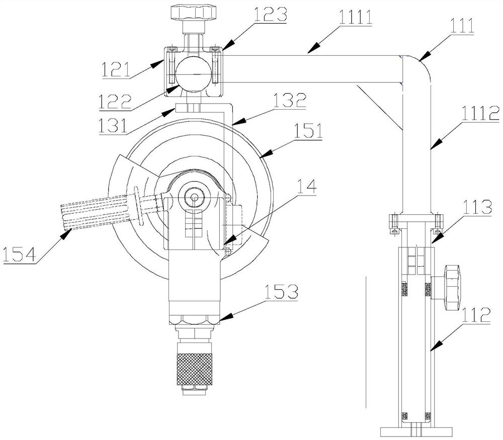
[0050] Such as Figure 1 to Figure 7 As shown, the embodiment of the present invention provides a grinding device with an angle adjustment function, including a drive system 2 and a grinding tool system 1, the grinding tool system 1 is fixed on the drive system 2, and the grinding tool system 1 includes The universal adjusting device and the grinding tool, one end of the universal adjusting device is fixedly connected with the drive system 2, and the other end of the universal adjusting device is rotatably connected with the grinding tool. The universal adjustment device is respectively connected with the drive system 2 and the abrasive tool, which not only realizes the adjustment of the angle of the abrasive tool according to the needs of the operator, but also realizes 360-degree grinding without dead ends, and can also adjust the abrasive tool under the drive of the drive system 2 In order to better meet the fine grinding operation requirements of different heights of rail ...

Embodiment 2

[0065] Such as figure 1 and image 3 As shown, the embodiment is a further limitation of the first embodiment above. In this embodiment, the drive system 2 is installed on the carrier system 3. The drive system 2 includes a horizontal moving device, and the horizontal moving device includes a support plate 25 extending in the vertical direction. The bottom of the support plate 25 is fixedly connected with the carrying system 3 , the support plate 25 is provided with a first slide rail 21 extending in the horizontal direction, and one end of the universal adjustment device is installed with a first slide block 22 correspondingly inserted into the first slide rail 21 . The horizontal moving device includes a first slide rail 21 and a first slide block 22, the universal adjustment device is fixedly connected with the first slide block 22, and the universal adjustment device moves horizontally along the first slide rail 21 through the first slide block 22, realizing The lateral f...

Embodiment 3

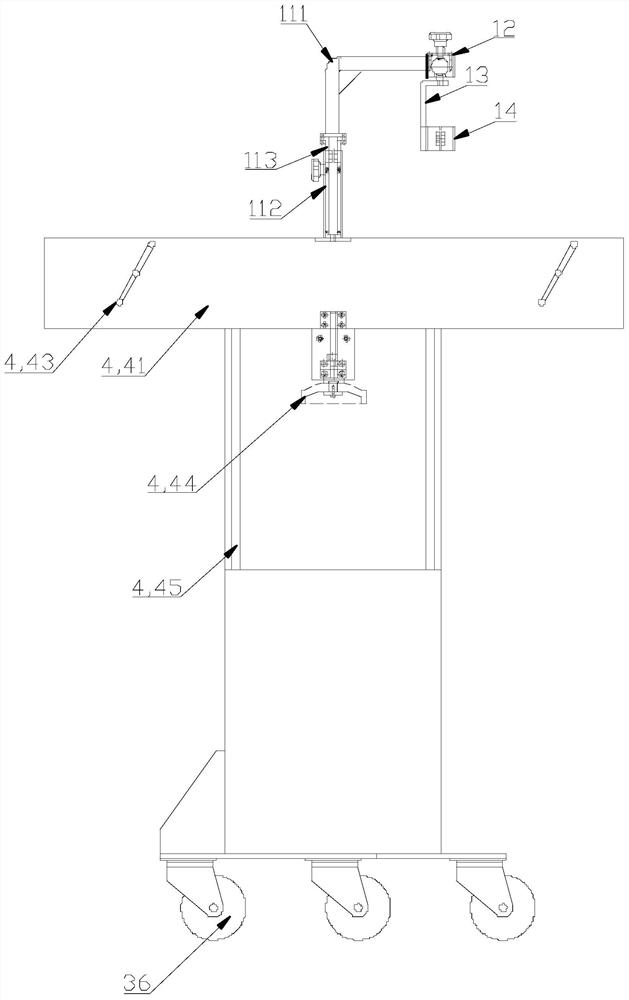
[0071] Such as Figure 1 to Figure 7 As shown, the embodiment is a further limitation of the second embodiment above. In this embodiment, it also includes a clamping mechanism for fixing the workpiece. The clamping system 4 is fixed on the carrier system 3. The clamping system 4 includes a front side plate 41 And rear side plate 42, front side plate 41 and rear side plate 42 are fixedly connected by tightening connecting rod 43, and tightening connecting rod 43 can adjust the gap between front side plate 41 and rear side plate 42, to realize according to the workpiece The width adjusts the gap between the front side panel 41 and the rear side panel 42 .

[0072] In this embodiment, a spring is provided between the front side plate 41 and the rear side plate 42, and the tightening link 43 passes through the front side plate 41, the spring and the rear side plate 42 in turn, so that the front side plate 41 and the rear side plate 42 is fixedly connected, and the gap between the...


PUM


Abstract

The invention discloses grinding equipment with an angle adjusting function. The grinding equipment with the angle adjusting function comprises a driving system and a grinding tool system, wherein thegrinding tool system is fixed to the driving system, the grinding tool system comprises a universal adjusting device and a grinding tool, one end of the universal adjusting device is fixedly connected with the driving system, and the other end of the universal adjusting device is rotationally connected with the grinding tool. According to the grinding equipment with the angle adjusting function,by arranging the universal adjusting device, the angle of the grinding tool can be adjusted according to needs, then 360-degree dead-corner-free grinding is achieved, the use requirements of differentoperators are met, the operators can work in good postures, and the labor intensity of the operators is reduced, and meanwhile, the grinding tool system is fixed to the driving system, the driving system drives the grinding tool system to move in the horizontal direction or the vertical direction so that the grinding tool system can be adjusted according to the position of a workpiece, and practicability is better.

Description

technical field [0001] The invention relates to the technical field of mechanical equipment, in particular to a grinding equipment with an angle adjustment function. Background technique [0002] With the development of social technology and economy, subways and high-speed rails have been introduced into development and put into operation one after another, making my country's rail transit an important step in the leap-forward development process, especially the rapid development of domestic and foreign high-speed rail lines and subways. The demand for rail vehicles is increasing year by year, which also puts forward higher requirements for the manufacturing and processing of various rail transit passenger car bodies, requiring the production process to be more sustainable and the product quality to better meet the safety requirements of modern rail transit. [0003] Rail vehicles are manufactured by splicing and welding block components. First, use milling equipment to rough...

Claims


Application Information

Patent Timeline
Patent Type & Authority Applications(China)
IPC IPC(8): B24B23/02B24B23/00B24B41/02B24B27/033
CPCB24B23/028B24B23/005B24B41/02B24B27/033
Inventor 盖金广杜云龙林凯
Owner CRRC QINGDAO SIFANG CO LTD
Why Eureka
Try Eureka