Permanent magnet motor stator

A permanent magnet motor and stator technology, applied in the direction of magnetic circuits, electrical components, electromechanical devices, etc., can solve the problems of low production efficiency, uncompact structure, large interval width, etc., and achieve high production efficiency, compact structure, and small interval width Effect

Pending Publication Date: 2021-05-25
SUZHOU SHENGYI MOTOR
View PDF0 Cites 0 Cited by
  • Summary
  • Abstract
  • Description
  • Claims
  • Application Information

AI Technical Summary

Problems solved by technology

However, in the prior art, the welding equipment for left and right spot welding has complex structure, inconvenient operation, and low production efficiency
[0006] 3) The winding lead-out wires of the above-mentioned permanent magnet motor stator are often located at the outermost periphery of the iron core, and they are parallel to the axis of the stator, which results in a large interval between the winding lead-out wires, which not only causes The structure is not compact, which also brings inconvenience to spot welding

Method used


Image

  • Permanent magnet motor stator
  • Permanent magnet motor stator
  • Permanent magnet motor stator

Examples


Embodiment

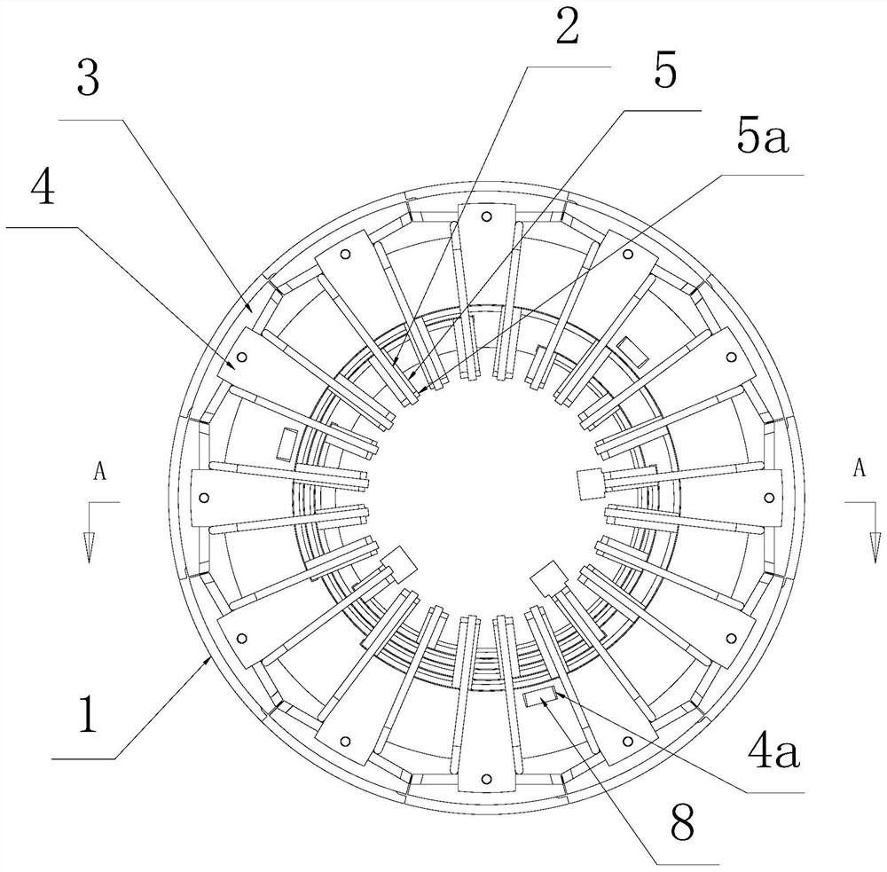
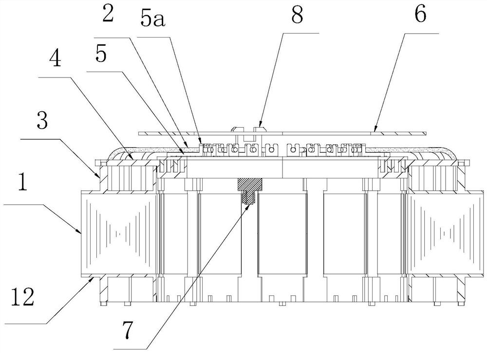
[0025] Embodiment: combine below Figure 1~Figure 3 The specific implementation of the permanent magnet motor stator provided by the present invention is described as follows:

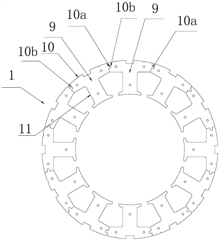
[0026] The stator of this permanent magnet motor is the same as the conventional technology, and its whole consists of a stator core 1, a winding wound on each tooth portion 11 inside the stator core 1, and a wiring structure for connecting the winding lead-out wire 2 with the power line. and Hall components together. The stator core 1 in this embodiment is a segmented stator core formed by annular splicing of twelve core unit blocks 9, and each core unit block 9 is composed of a peripheral yoke part 10 and a yoke part 10 connected teeth 11 constitute a specific combination image 3 As shown, the two sides of the yoke part 10 of each iron core unit block 9 are respectively provided with a convex key 10a and a groove 10b matching the convex key 10a, and two adjacent iron core unit blocks 9 on the circ...


PUM


Abstract

The invention discloses a permanent magnet motor stator, which comprises a stator iron core, windings wound on tooth parts on the inner side of the stator iron core, and a wiring structure used for connecting winding outgoing lines with power lines, wherein the wiring structure comprises an upper insulating frame fixed at the top of the stator core, a wiring disc fixed on the upper insulating frame and provided with a central hole, and wiring terminals distributed on the wiring disc and used for being welded with winding outgoing lines one by one. The motor stator is characterized in that winding outgoing lines of the stator core are bent towards the surface of the patch board and then are welded and fixed with the wiring terminals arranged on the inner circumference of the patch board one by one. According to the wiring structure of the stator, the winding outgoing line and the wiring terminal are easier to weld, so that the whole stator is easier to manufacture, the production cost is lower, and the production efficiency is higher.

Description

technical field [0001] The invention relates to a permanent magnet motor stator. Background technique [0002] The composition of the known permanent magnet motor stator usually includes a stator core, windings wound on each tooth of the stator core, and a wiring structure for connecting the winding lead wires to the power lines, and the subdivision of the wiring structure includes fixing An insulating frame at one end of the iron core, a junction plate arranged on the insulating frame, and several connection terminals distributed on the junction plate for welding with the winding lead-out wires one by one. [0003] However, in the existing wiring structure of the above-mentioned permanent magnet motor stator, the direction of the winding lead-out line is usually parallel to the axis line of the stator, and the connecting terminals on the corresponding terminal board are often distributed on the periphery of the terminal board, and vertical In the end face layout of the wir...

Claims


Application Information

Patent Timeline
Patent Type & Authority Applications(China)
IPC IPC(8): H02K1/12H02K1/14H02K3/50H02K3/38H02K11/215
CPCH02K1/12H02K1/148H02K3/38H02K3/50H02K11/215
Inventor 温群峰
Owner SUZHOU SHENGYI MOTOR
Why Eureka
Try Eureka