Prefabricated block for switch box and socket box of infilled wall masonry

A prefabricated block and switch box technology, applied in the direction of walls, building components, buildings, etc., can solve the problems of high cost and cost of slotted holes, difficult to control the size and shape of the slotted holes, plastering cracks, etc., so as to reduce the later maintenance cost and appearance. Good look and feel and the effect of improving quality

Inactive Publication Date: 2021-06-04
MCC5 GROUP CORP SHANGHAI
View PDF3 Cites 0 Cited by
  • Summary
  • Abstract
  • Description
  • Claims
  • Application Information

AI Technical Summary

Problems solved by technology

However, there are many shortcomings in this method. The shape and size of the grooves excavated in the wall are uneven and irregular, which makes it difficult to install later, and it is easy to cause cracks in the blocks of the wall, which will seriously cause the blocks in this part to break.
The size and shape of the excavated slots are difficult to control, which makes it difficult and not dense to seal the wall openings after the switch box and socket box are installed later
In addition, the vibration generated during the slotting process will easily lead to cracks on the wall surface and loose masonry, which will easily cause cracks in the later plastering, increasing maintenance costs, and the cost of slotting is relatively high
[0003] Therefore, there are above-mentioned inconveniences and problems in the known secondary digging out switch box or socket box groove hole mode.

Method used


Image

  • Prefabricated block for switch box and socket box of infilled wall masonry
  • Prefabricated block for switch box and socket box of infilled wall masonry
  • Prefabricated block for switch box and socket box of infilled wall masonry

Examples


Embodiment 1

[0025] The switch box and socket box prefabricated blocks for filling wall masonry of the present invention are determined according to the length, width and height of the switch box and socket box body as a, b, and c respectively Dimensions, including filling wall masonry switch box, socket box prefabricated block body.

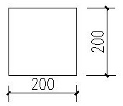
[0026] see now Image 6 , Image 6 It is a three-dimensional schematic diagram of a switch or a socket box according to an embodiment of the present invention, in which a is the length of the switch or the socket box, b is the width of the switch or the socket box, and c is the height of the switch or the socket box. As shown in the figure, the main body of the prefabricated block of the masonry switch box and socket box of the filled wall is a concrete prefabricated block with a length of 240mm, a width of 200mm, and a height of 200mm. There is a groove inside the block to accommodate the switch box and the socket box body, wherein: the length of the groo...

Embodiment 2

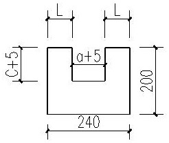
[0029] Figure 7 It is a structural schematic diagram of a prefabricated block according to an embodiment of the present invention. The preparation method of the present invention for filling wall masonry switch box, socket box prefabricated block:

[0030] Step 1. Technical preparation: sort out the switch boxes and socket box slots in the masonry infill wall on the drawings, make statistics, and preliminarily estimate the quantity; determine the specific size of the switch box and socket box according to the electrical construction drawing.

[0031] Step 2. Mold making, use 1mm thick steel plate to cut into small pieces of steel plate of different shapes and sizes according to the size, and accurately weld and process it into a mold with grooves according to the design size of the mold; after the welding is completed, the welding edge of the mold is polished to ensure the processing The welding part is smooth and straight, and the final processing is completed to shape the ...

Embodiment 3

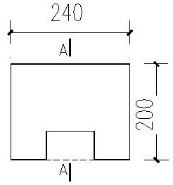
[0036] Figure 8 It is a schematic diagram of the use state of the prefabricated block in the embodiment of the present invention. The use method of the present invention for filling wall masonry switch boxes and socket box prefabricated blocks:

[0037] Step 1. Combined with the masonry brick arrangement diagram and disclosure content, move the prefabricated blocks to the corresponding location according to the specific needs of the floor.

[0038] Step 2. When building to the elevation of the switch box and socket box, according to the position of the exposed wire tube reserved in the structure, lay the prefabricated block at the corresponding position to ensure that the groove of the prefabricated block is on the same line as the reserved wire tube It is convenient for the wire pipe to be connected to the installed switch box and socket box in the later stage.

[0039] Step 3. When the wall is a switch box, the groove of the block faces upward; if it is a socket box, the ...


PUM


Abstract

The invention relates to a prefabricated block for a switch box and a socket box of an infilled wall masonry. The prefabricated block comprises a prefabricated block body for the switch box and the socket box of the infilled wall masonry, and is characterized in that the prefabricated block body for the switch box and the socket box of the infilled wall masonry is a concrete prefabricated block with the length of 240 mm, the width of 200 mm and the height of 200 mm; a groove for accommodating a switch box body and a socket box body is arranged in a concrete prefabricated block body between the length-direction surface and the top surface of the concrete prefabricated block; one surface of the groove is communicated with the length-direction surface of the concrete prefabricated block; and the other surface of the groove is communicated with the top surface of the concrete prefabricated block. The prefabricated block for the switch box and the socket box of the infilled wall masonry has the advantages that the prefabricated block is simple in structure and convenient to manufacture, materials are saved, the phenomena of wall cracking, building block breakage and the like caused by the fact that a wall body is damaged by slotting holes formed in the rear portion of a masonry infilled wall are effectively avoided, one-time forming of a masonry project is guaranteed, a wall surface is neat, the appearance quality is good, and the quality of a masonry project is improved.

Description

technical field [0001] The invention relates to a concrete prefabricated block, in particular to a prefabricated block used for filling wall masonry switch boxes and socket boxes. Background technique [0002] In the construction of civil construction projects, some switch boxes and socket boxes are designed in the post-filling wall. The traditional method is to make a second slot on the corresponding position of the wall after the masonry is completed, and dig out the switch box or socket box groove. Hole. However, there are many shortcomings in this method. The shape and size of the grooves excavated in the wall are uneven and irregular, which makes it difficult to install in the later stage, and it is easy to cause cracks in the blocks of the wall, and seriously, it will cause the blocks in this position to break. The size and shape of the excavated slots are difficult to control, which makes it difficult and not dense to seal the wall openings after the switch box and s...

Claims


Application Information

Patent Timeline
Patent Type & Authority Applications(China)
IPC IPC(8): E04C1/39E04B2/02
CPCE04C1/39E04B2/02
Inventor 陶胜
Owner MCC5 GROUP CORP SHANGHAI
Why Eureka
Try Eureka