A plug-in machine for motor rotor terminals

A technology for connecting terminals and motor rotors, which is used in electrical components, electric components, and manufacturing of motor generators, etc., can solve the problems of difficult to achieve continuous plug-in operation, low production and processing efficiency, and uneven quality of finished products. Improve production and processing efficiency, improve production and processing efficiency, and stabilize the quality of finished products

Active Publication Date: 2022-02-08
重庆市美庆科技有限公司
View PDF0 Cites 0 Cited by
  • Summary
  • Abstract
  • Description
  • Claims
  • Application Information

AI Technical Summary

Problems solved by technology

[0002] The motor rotor is mainly composed of rotor core, rotor winding, rotating shaft and terminals. The terminals are installed in the preset holes in the rotor by plugging, and then can be formed by pressing. At present, most motor rotor manufacturers still use Manually complete the plug-in operation, the production efficiency is low, and the quality of the actual finished product is uneven due to manual errors, and some machines with automatic plug-in functions are difficult to achieve continuous plug-in operations. Although the labor input is reduced, the production and processing The efficiency is still not high, which is not conducive to promotion and use

Method used


Image

  • A plug-in machine for motor rotor terminals
  • A plug-in machine for motor rotor terminals
  • A plug-in machine for motor rotor terminals

Examples


Embodiment 1

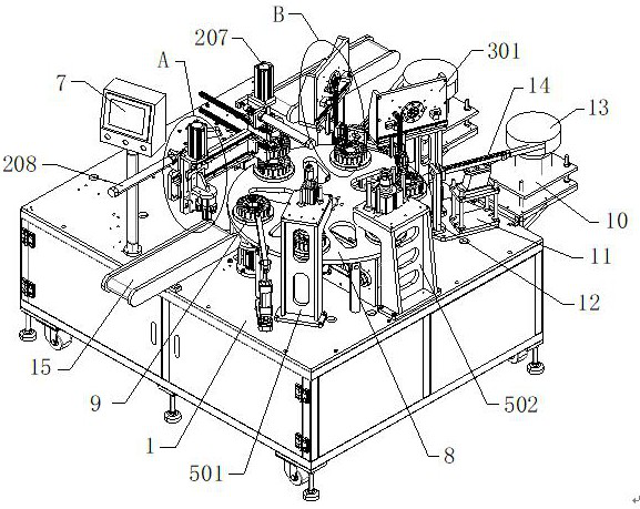
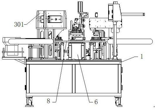
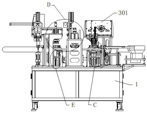
[0028] see Figure 1-10 , the present invention provides a technical solution: a plug-in machine for motor rotor terminals, including a frame 1, which is provided with a feeding and discharging mechanism 2, a plug-in mechanism 3, a top mold rotating mechanism 4 and a pressing mechanism 5. The servo motor 6 and the main control panel 7 are fixedly installed on the top of the frame 1, and the output shaft of the servo motor 6 is fixedly installed with a turntable 8 through a coupling. The top of the turntable 8 is provided with six sets of installation holes distributed in a circular array , the rotor tray 9 is installed in the installation hole, the rear side of the frame 1 is fixedly installed with two sets of mounting platforms 10, the top of the frame 1 is fixedly installed with two sets of support frames 11, and the tops of the mounting platforms 10 and support frames 11 are respectively A feeding vibrating plate 13 and a baffle plate 12 are fixedly installed, and a feeding...

Embodiment 2

[0032] see Figure 1-10 , on the basis of Embodiment 1, the feeding and discharging mechanism 2 includes a mounting plate 201, a first guide rail 202, a first sliding seat 203, a mounting seat 204, a support 205, a first clamping cylinder 206, a first cylinder 207, a hydraulic pressure Rod 208 and connecting block 209, two sets of mounting plates 201 are erected above the frame 1 and are vertically distributed above the two sets of conveyor belts 15, and two sets of first guide rails 202 are fixedly installed on the outer wall of one side of the mounting plate 201, One side of the mounting plate 201 is provided with a mounting seat 204, and two groups of first sliding seats 203 are fixedly installed on one side of the mounting seat 204. The first sliding seats 203 are slidably installed on the first guide rail 202. The seat 204 is slidingly installed, and a guide rail is fixedly installed on the outer wall of the other side of the mounting seat 204. A support 205 is slidably i...


PUM


Abstract

The invention discloses a plug-in machine for connecting terminals of motor rotors, and relates to the technical field of motor rotor production. The plug-in machine for motor rotor terminals includes a frame. The frame is provided with a feeding and discharging mechanism, a plug-in mechanism, a top mold rotating mechanism and a pressing mechanism. The top of the frame is fixedly installed with a servo motor and a main control. The panel, the output shaft of the servo motor is fixedly installed with a turntable through a coupling. The plug-in machine for motor rotor terminals automatically inserts multiple groups of terminals onto the motor rotor accurately and without error. Compared with manual plugging, on the one hand, it can reduce the labor intensity of operators and reduce labor input. On the other hand, the machine has high precision, the overall pass rate has been significantly improved, and the quality of the actual formed motor rotor is stable. At the same time, the machine can continuously perform inserting, pressing, and loading and unloading operations, which greatly improves production. Processing efficiency.

Description

technical field [0001] The invention relates to the technical field of motor rotor production, in particular to a plug-in machine for motor rotor terminals. Background technique [0002] The motor rotor is mainly composed of rotor core, rotor winding, rotating shaft and terminals. The terminals are installed in the preset holes in the rotor by plugging, and then can be formed by pressing. At present, most motor rotor manufacturers still use Manually complete the plug-in operation, the production efficiency is low, and the quality of the actual finished product is uneven due to manual errors, and some machines with automatic plug-in functions are difficult to achieve continuous plug-in operations. Although the labor input is reduced, the production and processing The efficiency is still not high, which is not conducive to promotion and use. Contents of the invention [0003] The purpose of the present invention is to provide a plug-in machine for motor rotor terminals, so ...

Claims


Application Information

Patent Timeline
Patent Type & Authority Patents(China)
IPC IPC(8): H02K15/00H02K15/02
CPCH02K15/0062H02K15/02H02K15/026
Inventor 刘文刘庆辉
Owner 重庆市美庆科技有限公司
Why Eureka
Try Eureka