Antenna and electronic equipment

A technology for electronic equipment and antennas, applied to antennas, antenna parts, antenna grounding devices, etc., to solve problems such as insufficient space and deterioration of antenna performance

Active Publication Date: 2021-07-16
HUAWEI TECH CO LTD
View PDF13 Cites 0 Cited by
  • Summary
  • Abstract
  • Description
  • Claims
  • Application Information

AI Technical Summary

Problems solved by technology

As this distance (headroom) gradually decreases, the antenna performance will deteriorate sharply
[0004] According to the above situation, the space provided for the antenna in the electronic equipment is already insufficient. If more antennas are to be added, it will bring great challenges to the design of the antenna

Method used


Image

  • Antenna and electronic equipment
  • Antenna and electronic equipment
  • Antenna and electronic equipment

Examples


Embodiment Construction

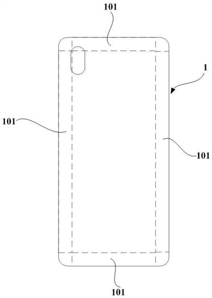
[0046] In order to facilitate understanding of the antenna provided in the embodiment of the present application, the specific application scenarios thereof are first described below. The antennas of the embodiments of the present application can be applied to various electronic devices. Exemplary, but not limited to, electronic devices may be mobile phones, tablet computers, smart wearable devices, or personal digital assistants (PDAs). The above-mentioned electronic devices all need to transmit signals through antennas. Taking the electronic device as a mobile phone as an example, refer to figure 1 , the antenna is usually disposed on the edge area 101 of the electronic device, so as to improve the radiation efficiency of the antenna.

[0047] In order to comply with the development requirements of the communication of the electronic device 1 , more and more antennas need to be arranged in the electronic device 1 . Due to the limited space available in the edge area 101 of ...


PUM


Abstract

The invention provides an antenna and electronic equipment, and relates to the technical field of antennas. The antenna is of a flat metal pipeline type structure with two open ends, wherein the top surface of the antenna is set as a grounding reference surface for feeding, the top surface of the antenna is provided with a gap, the antenna is in an open circuit state at the gap, the top surface is also provided with a grounding point, the antenna further comprises a feeder line, the feeder line is arranged in the antenna, the two ends of the feeder line are arranged on the two sides of the gap respectively, one end of the feeder line is provided with a feeding point, the feeding point and the grounding point form a feeding port, the other end of the feeder line extends freely, the antenna further comprises a bottom surface arranged opposite to the top surface, and the ground can be connected with metal ground. The antenna provided by the embodiment of the invention can be arranged on the grounding structural member of the electronic equipment, so that the problem of insufficient antenna arrangement space in the electronic equipment can be solved.

Description

technical field [0001] The present application relates to the technical field of antennas, and in particular to an antenna and electronic equipment. Background technique [0002] In recent years, in order to meet the needs of the communication market, there are more and more antennas in electronic equipment. In particular, the start of 5G communication will add 4-8 multiple-input-multi-output (MIMO) antennas to the mobile phone. [0003] At present, in order to make the antenna have good radiation efficiency, the antenna is basically distributed on the edge of the electronic equipment. The middle area inside the body of electronic equipment, such as above the battery, has always been a forbidden area for antennas. The main reason is that most of the antennas in electronic equipment adopt ground-clearance antennas, such as inverted-F antennas (inverted-Fantenna, IFA) and T-type antennas. These antennas cannot be placed directly on grounded metal structures. Keep a certain...

Claims


Application Information

Patent Timeline
Patent Type & Authority Applications(China)
IPC IPC(8): H01Q1/24H01Q1/36H01Q1/48H01Q1/50
CPCH01Q1/242H01Q1/50H01Q1/48H01Q1/36H01Q1/24
Inventor 马国忠孙树辉刘深鹏梁娇陈峰文邹真林
Owner HUAWEI TECH CO LTD
Why Eureka
Try Eureka