A two-valve thin-shell type high-stability integrated structure

A high-stability, thin-shell technology, applied in machine/stand, supporting machine, mechanical equipment, etc., can solve the destruction of high-stability integrated structural integrity, structural rigidity, strength, micron-level thermal stability characteristics and camera installation requirements Conflict and other problems, to achieve the effect of shortening the force transmission path and ensuring the maintenance of integrated deformation

Active Publication Date: 2019-04-09
BEIJING INST OF SPACECRAFT SYST ENG
View PDF5 Cites 0 Cited by
  • Summary
  • Abstract
  • Description
  • Claims
  • Application Information

AI Technical Summary

Problems solved by technology

Considering the layout of the primary mirror, secondary mirror, and third mirror of the optical load, in order to meet the installation requirements of the optical load, the high-stable integrated structure not only needs to provide the camera with an integrated mounting plane for the camera and star sensor, but also needs to meet the needs of the camera’s primary mirror, three mirrors, etc. The layout and space requirements of the mirror and some supporting optical equipment may destroy the integrity of the high-stable integrated structure, that is, the contradiction and conflict between the rigidity, strength, and micron-level thermal stability of the highly-stable integrated structure and the installation requirements of the camera. Comprehensively consider the above factors to carry out high stability integrated structure design

Method used


Image

  • A two-valve thin-shell type high-stability integrated structure
  • A two-valve thin-shell type high-stability integrated structure
  • A two-valve thin-shell type high-stability integrated structure

Examples


Embodiment Construction

[0031] The present invention will be further described below in conjunction with the accompanying drawings.

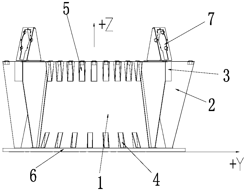
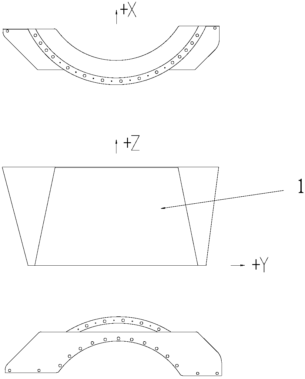
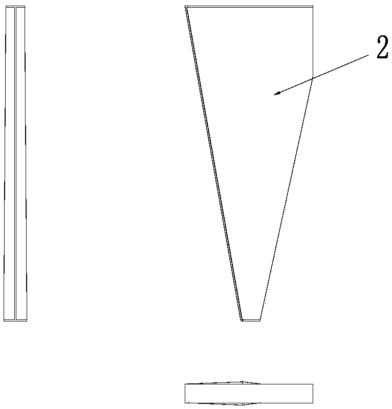
[0032] Such as figure 1 , Figure 10 As shown, a two-valve thin-shell high-stability integrated structure includes shell flaps 1, reinforcing ribs 2, reinforced cover plates 3, reinforced corner boxes 4, reinforced corner boxes 5, honeycomb bottom plate 6, star-sensitive bracket 7, Connecting piece 8 with camera, connecting piece 9 with star sensitive bracket, upper end surface 10.

[0033] All the parts are glued together, and the reinforced corner box 4, the reinforced corner box 5 and the semi-conical shell flap 1 are glued together and anti-stripping screws are added.

[0034] Each shell flap 1 is installed symmetrically with respect to the symmetrical axis of the honeycomb bottom plate 6. The upper part of the shell flap 1 is connected to the upper end surface 10, and the lower part is connected to the honeycomb bottom plate 6; the reinforcing ribs 2 are install...


PUM


Abstract

A two-section thin shell type high-stability integrated structure comprises shell section sheets, strengthening ribs, strengthening cover plates, upper strengthening corner boxes, lower strengtheningcorner boxes, a honeycomb bottom plate, a star sensor support, a camera connecting piece and an upper end face. The shell section sheets are symmetrically arranged relative to the symmetry axis of thehoneycomb bottom plate. The upper portions of the shell section sheets are connected with the upper end face, and the lower portions of the shell section sheets are connected with the honeycomb bottom plate. The strengthening ribs are arranged on the two sides of the shell section sheets. The upper strengthening corner boxes are distributed at the included angle position between the upper end face and the surfaces of the shell section sheets in the circumferential direction, and the lower strengthening corner boxes are distributed at the included angle position between the surfaces of the shell section sheets and the honeycomb bottom plate in the circumferential direction. The star sensor support and the camera connecting piece are arranged on the upper end face, and the strengthening cover plates are arranged in the included angles between the side faces of the strengthening ribs and the upper end face. Through the two-section thin shell type structure, sufficient layout space is provided for an optical camera, meanwhile, an integrated installing plane is provided for the optical camera and the star sensor support, and the requirements for rigidity, strength and micron-order heatstability design are met.

Description

technical field [0001] The invention relates to an integrated support structure. Background technique [0002] With the increasing requirements for the indicators of the earth and sky observation spacecraft, high image positioning accuracy has become a typical feature of high-performance remote sensing spacecraft. On-orbit structural deformation directly affects the spatial orientation and geometric relationship between key components such as cameras, star sensors, and gyroscopes, and even affects the spatial positional relationship between lenses inside the camera, which is an important factor in determining image positioning accuracy and camera imaging quality. one. The displacement caused by the thermal deformation of the structure on the orbit is generally on the order of microns. For low-resolution observation spacecraft, these disturbances can be ignored; The impact may directly determine whether the imaging quality can reach the design target. In general, micron-le...

Claims


Application Information

Patent Timeline
Patent Type & Authority Patents(China)
IPC IPC(8): F16M11/04F16M11/16
Inventor 刘国青阮剑华白刚李竞蔚张立新赵华余快李果杨文涛王成伦沈中刘凤晶李响王丽俐
Owner BEIJING INST OF SPACECRAFT SYST ENG
Why Eureka
Try Eureka