Device for automatically changing exhaust direction according to wind direction to avoid direct blowing for power distribution cabinet

A power distribution cabinet and wind direction technology, which is applied in substation/power distribution device housing, substation/switchgear cooling/ventilation, electrical components, etc., can solve the problem that the angle of cooling holes cannot be controlled, and the cooling holes of power distribution cabinets cannot be automatically controlled Open and close problems, to achieve the effect of changing the exhaust direction and enhancing the heat dissipation effect

Inactive Publication Date: 2021-09-07
苏坤鹏
View PDF0 Cites 0 Cited by
  • Summary
  • Abstract
  • Description
  • Claims
  • Application Information

AI Technical Summary

Problems solved by technology

[0003] When the power distribution cabinet is used in rainy and snowy weather, it is easy to enter the inside of the power distribution cabinet due to the wind blowing rain and snow, especially the wind directly blows the heat dissipation holes of the power distribution cabinet, and the heat dissipation holes of the power distribution cabinet cannot be automatically opened and closed, nor can they be controlled The angle of the cooling holes makes it difficult to prevent the wind from blowing rain and snow into the power distribution cabinet. Therefore, we provide a device for power distribution cabinets that automatically changes the exhaust direction according to the wind direction to avoid direct blowing

Method used


Image

  • Device for automatically changing exhaust direction according to wind direction to avoid direct blowing for power distribution cabinet
  • Device for automatically changing exhaust direction according to wind direction to avoid direct blowing for power distribution cabinet
  • Device for automatically changing exhaust direction according to wind direction to avoid direct blowing for power distribution cabinet

Examples


Embodiment 1

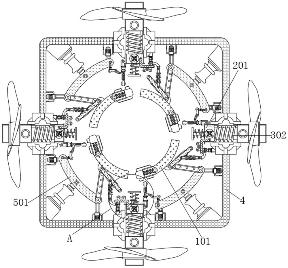
[0022] see Figure 1-3 , a device for a power distribution cabinet that automatically changes the exhaust direction according to the wind direction to avoid direct blowing, including a steering mechanism 1. A casing 4 is movably connected to the surface of the mechanism 3 , and a booster mechanism 5 is movably connected to the surface of the transmission mechanism 2 .

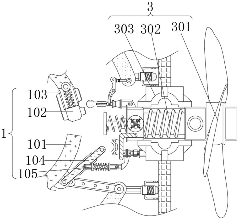
[0023] The inside of the steering mechanism 1 includes an installation barrel 101, a spacer 102, a spring 103, a push rod 104, and a tension spring 105. The surface of the installation barrel 101 is provided with a vent hole, and the spacer 102 is movably connected to the surface of the vent hole of the installation barrel 101. The two ends of spring 103 are respectively fixedly connected on the surface of installation bucket 101 and spacer 102, and one end of push rod 104 is movably connected on the surface of installation bucket 101, and one end of extension spring 105 is movably connected on the surface of p...

Embodiment 2

[0026] see Figure 4 , a device for a power distribution cabinet that automatically changes the exhaust direction according to the wind direction to avoid direct blowing. A casing 4 is movably connected to the surface of the mechanism 3 , and a booster mechanism 5 is movably connected to the surface of the transmission mechanism 2 .

[0027] The interior of the booster mechanism 5 includes a flexible plate 501, a pull rod 502, a telescopic rod 503, a support rod 504, and a rotating rod 505. One end of the pull rod 502 is movably connected to one end of the flexible plate 501, and one end of the rotating rod 505 is movably connected to the rotating rod. The other end of 505 , one end of support rod 504 is fixedly connected to the midpoint of flexible board 501 , and one end of telescopic rod 503 is fixedly connected to the end of flexible board 501 close to pull rod 502 .

[0028] One end of the flexible plate 501 close to the pull rod 502 moves inwardly, and the other end of ...

Embodiment 3

[0030] see Figure 1-5 , a device for a power distribution cabinet that automatically changes the exhaust direction according to the wind direction to avoid direct blowing, including a steering mechanism 1, and the inside of the steering mechanism 1 includes a mounting bucket 101, a spacer 102, a spring 103, a push rod 104, and a tension spring 105 , the surface of the installation bucket 101 is provided with a ventilation hole, the spacer 102 is movably connected to the surface of the ventilation hole of the installation bucket 101, the two ends of the spring 103 are respectively fixedly connected to the surface of the installation bucket 101 and the spacer 102, and one end of the push rod 104 is movable It is connected to the surface of the installation barrel 101 , and one end of the extension spring 105 is movably connected to the surface of the push rod 104 .

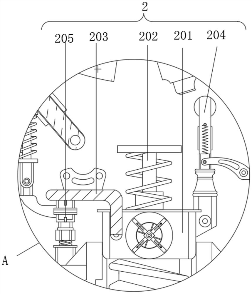
[0031] The surface of the steering mechanism 1 is movably connected with a transmission mechanism 2, and the int...


PUM


Abstract

The invention relates to the technical field of intelligent power distribution cabinets, and discloses a device for automatically changing the exhaust direction according to the wind direction to avoid direct blowing for a power distribution cabinet, and the device comprises a steering mechanism. The surface of the steering mechanism is movably connected with a transmission mechanism, the surface of the transmission mechanism is movably connected with a trigger mechanism, and the surface of the trigger mechanism is movably connected with a shell. The surface of the transmission mechanism is movably connected with a pressurizing mechanism, an impeller and a lead screw are coaxially rotated by blowing the impeller, a threaded ring is driven to move inwards along the threaded ring and the lead screw, and the surface of a zigzag rod inclines inwards to push a push rod, so that a mounting barrel rotates. Vent holes in the surface of the mounting barrel and through holes in the surface of the shell are staggered, through the rotation of the mounting barrel, one end, close to the pull rod, of a flexible plate moves inwards, the other end, away from the pull rod, of the flexible plate is driven to move towards the inner wall of the shell, so that air pressure difference is generated between the interior of the mounting barrel and the end, away from the pull rod, of the flexible plate, and the heat dissipation effect is enhanced.

Description

technical field [0001] The invention relates to the technical field of intelligent power distribution cabinets, in particular to a device for a power distribution cabinet that automatically changes the exhaust direction according to the wind direction to avoid direct blowing. Background technique [0002] The power distribution cabinet (box) is divided into power distribution cabinet (box), lighting distribution cabinet (box), metering cabinet (box), and is the final equipment of the power distribution system. The cabinet is used in the occasions where the load is relatively scattered and there are few circuits; the motor control center is used in the occasions where the load is concentrated and there are many circuits. [0003] When the power distribution cabinet is used in rainy and snowy weather, it is easy to enter the inside of the power distribution cabinet due to the wind blowing rain and snow, especially the wind directly blows the heat dissipation holes of the power...

Claims


Application Information

Patent Timeline
IPC IPC(8): H02B1/56H02B1/28H02B1/54H02B1/32
CPCH02B1/565H02B1/28H02B1/54H02B1/32
Inventor 苏坤鹏
Owner 苏坤鹏
Why Eureka
Try Eureka