Air guiding structure

A technology of air guide structure and components, which is applied in the direction of cooling/ventilation/heating transformation, instruments, electrical digital data processing, etc., and can solve the problems of complex structure and uncomfortable users in the adjustment of heat sinks

Active Publication Date: 2012-06-27
MSI ELECTRONICS KUN SHAN
View PDF5 Cites 3 Cited by
  • Summary
  • Abstract
  • Description
  • Claims
  • Application Information

AI Technical Summary

Problems solved by technology

[0003] In order to prevent foreign matter from entering the notebook computer through the air inlet or outlet, multiple fixed fins are provided at the air inlet or outlet, and most of the fins are perpendicular to the surface of the main casing, so that the wind direction blown by the air outlet is in line with the main casing. For example, the air outlet of the notebook computer is set on the side of the host, and the user's hand needs to be placed on the side of the corresponding air outlet of the notebook computer (such as operating the mouse), so that the hot air blown from the air outlet will Blowing directly to the user's hand will cause discomfort to the user
[0004] Of course, in order to solve the above-mentioned problems, the air outlet of the notebook computer can be set at the rear end of the host computer to prevent the hot air from blowing to the user's hand. The side of the mainframe still accounts for a considerable majority, or some notebook computer manufacturers have designed adjustable fins, such as the U.S. No. 6229701 patent which discloses a cooling fin structure for the air outlet of a notebook computer, and the U.S. No. 6229701 patent disclosed The heat sink is arranged at the air outlet in a rotatable relationship, which can be controlled by the user to cover the heat sink to the air outlet, or to open the heat sink at an angle. However, the adjustment method of the heat sink in US Patent No. 6229701 quite complex in structure

Method used


Image

  • Air guiding structure
  • Air guiding structure
  • Air guiding structure

Examples


Embodiment Construction

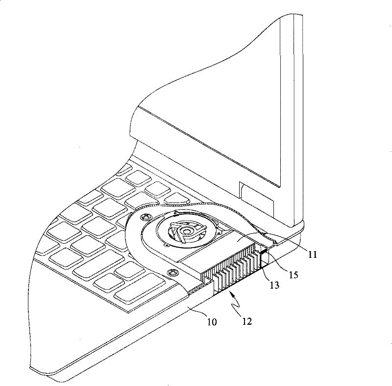
[0031] The air guide structure disclosed in the present invention is applied to electronic devices, wherein electronic devices refer to electronic devices that generate heat energy under operating conditions such as desktop computers, servers, and notebook computers, and in the following specific embodiments, Notebook computer is used as the preferred embodiment of the present invention.

[0032] Such as figure 1 As shown, the wind guiding structure disclosed in the present invention is applied to a notebook computer. The notebook computer is provided with a host 10 . The host 10 has a cooling fan 11 inside, and an air outlet 12 corresponding to the cooling fan 11 is provided on the side of the host 10 .

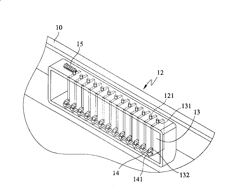
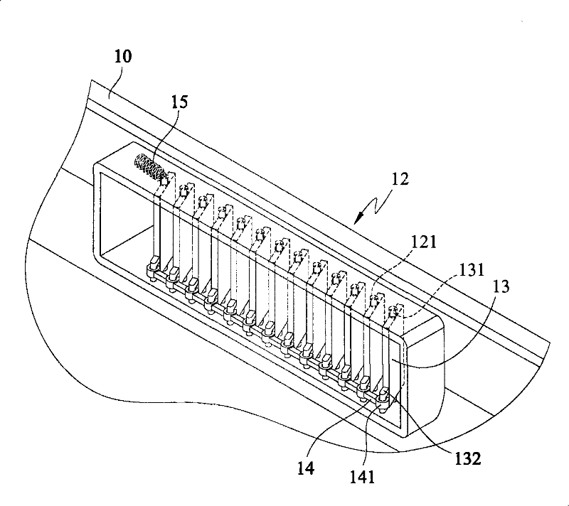
[0033] see further Figure 2A , Figure 2B , shown in the figure is the first embodiment of the present invention, according to the wind guiding structure disclosed in the first embodiment of the present invention, which includes a plurality of fins 13 , a detent member 1...


PUM


Abstract

The invention discloses an air guiding structure which is arranged on an air outlet of electronic equipment and comprises multi-chip fins and a memory deformation component, wherein, the multi-chip fins are arranged on the air outlet in a rotating manner; one end of the memory deformation component is fixed on the electronic equipment, and the other end thereof is connected to one of the multi-chip fins; the memory deformation component is heated to deform and pulls the multi-chip fins to swing together. The invention has the beneficial technical effects that: according to the air guiding structure disclosed by the invention, when the arranged electronic equipment generates heat due to operation, the memory deformation component is heated and expands to deform, immediately pushes the multi-chip fins to swing to a working angle, and leads the multi-chip fins to change air exhaust direction according to the temperature effect of the electronic equipment operation, thereby becoming an optimum design of the air guiding structure applied to electronic equipment.

Description

technical field [0001] The invention relates to an air guide structure, in particular to an air guide structure which changes the air outlet direction by utilizing temperature changes. Background technique [0002] Various electronic devices generate heat energy due to their operation, and in order to maintain the normal operation of the electronic devices, heat dissipation design is an important issue for the electronic devices. Take notebook computers as an example, the heat dissipation design of most notebook computers is that a cooling fan is installed inside the host, and an air inlet is provided on the top or bottom of the host, and an air outlet is provided on the side of the host. During operation, the cooling fan will suck the cold air from the outside from the air inlet, and after heat exchange with the heat source (such as the central processing unit) of the notebook computer, the cooling fan will blow the hot air out from the air outlet. [0003] In order to pre...

Claims


Application Information

Patent Timeline
Patent Type & Authority Patents(China)
IPC IPC(8): H05K7/20G06F1/20
Inventor 陈正隆
Owner MSI ELECTRONICS KUN SHAN
Why Eureka
Try Eureka