Transformer core structure and power transformer

A technology for power transformers and steel, applied in transformer/inductor cooling, transformer/inductor noise damping, transformer/inductor magnetic cores, etc., can solve the problems of uncontrollable transformer capacity and large load loss, and avoid cracking Or microscopic cracks, reduce loss, reduce the effect of voltage power

Active Publication Date: 2022-04-19
无锡市电力变压器有限公司
View PDF0 Cites 1 Cited by
  • Summary
  • Abstract
  • Description
  • Claims
  • Application Information

AI Technical Summary

Problems solved by technology

[0004] The object of the present invention is to provide a transformer core structure and power transformer that can effectively reduce losses, control the capacity of the transformer according to the power load, effectively cool the inside of the equipment, and reduce stray and auxiliary equipment losses. Transformer, in order to overcome the defects that the above-mentioned traditional transformer cannot control the capacity of the transformer according to the power load, and the load loss is large

Method used


Image

  • Transformer core structure and power transformer
  • Transformer core structure and power transformer
  • Transformer core structure and power transformer

Examples


Embodiment 1

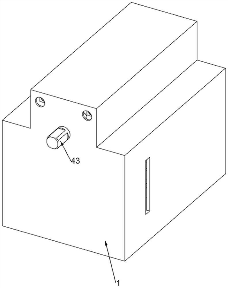
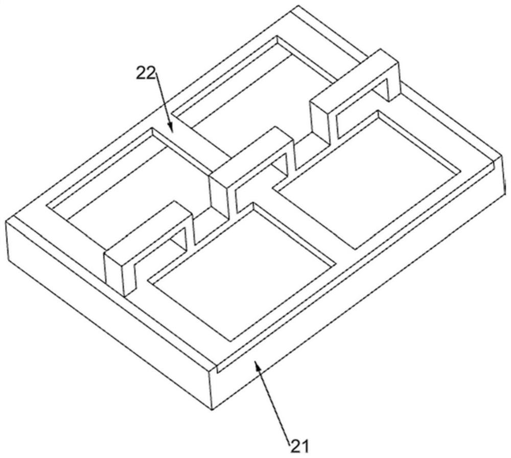
[0042] A transformer core structure and power transformer, such as Figure 1 、 Figure 2 、 Figure 3 、 Figure 4 、 Figure 5 、 Figure 6 、 Figure 7 、 Figure 8 、 Figure 9 、 Figure 10 、 Figure 11 、 Figure 17 and 18 Shown, comprising a housing 1, a bottom plate chamber 21, a slotted support frame 22, a pressure transformer member 3 and a regulating member 4, the shell 1 is fixedly installed with a bottom plate chamber 21, the bottom plate chamber 21 is fixedly installed with a slotted support frame 22, the pressure transformer member 3 is provided on the slotted support frame 22, the pressure change member 3 is provided with a regulating member 4.

[0043] The voltage transformer member 3 includes a silicon steel chip 31, a main coil 32, a separator plate 33, a secondary coil one 34, a secondary coil two 35, a secondary coil three 36, a terminal block 37 and a silicon steel terminal post 38, the slotted support frame 22 distributed is provided with three stacks of silicon steel chips 31, ...

Embodiment 2

[0048] On the basis of Example 1, e.g., Figure 7 、 Figure 8 and Figure 9 Shown, further comprising an oil injection member 5, the open hole support frame 41 is provided with an oil injection member 5, the oil injection member 5 comprises a P-type slotted frame 51, solenoid valve 52, oil guide 53, sector gear 54, L type rack rack 55, first reset spring 56, sliding tooth block 57, a second reset spring 58 and a magnetic valve switch 59, the open hole support frame 41 is fixed on two P type slotted frame 51, the P type slotted frame 51 above the solenoid valve 52, The electromagnetic valve 52 is connected to the oil guide pipe 53, the oil guide pipe 53 is connected to the two separators 33, the sector gear 54 is fixed to the lead screw 42, the P-type slotted rack 51 is vertically sliding connected to the L-type rack rack 55, the L-type rack rack 55 and the P-type slotted rack 51 is connected to the first reset spring 56, the L-type rack rack 55 above the sliding tooth block 57, the ...

Embodiment 3

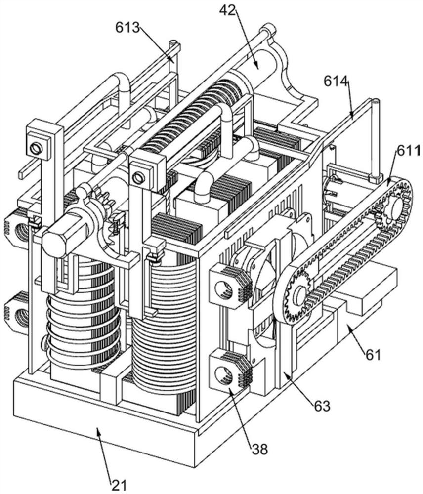
[0052] On the basis of Example 2, e.g., Figure 10 、 Figure 11 、 Figure 12 、 Figure 13 、 Figure 14 、 Figure 15 、 Figure 16 and Figure 17 Shown, further comprising a variable speed cooling member 6, the bottom plate chamber 21 side is provided with a variable speed cooling member 6, the variable speed cooling member 6 includes a fixed support block 61, servo motor 62, fan cover 63, glass fiber reinforced plastic fan 64, transmission gear 65, slotted bushing 66, sliding rod 67, first homing spring 68, sliding gear 69, second homing spring 610, elastic steel belt 611, L-type slotted frame 612, with rod curved sliding sleeve 613 and wedge push bar 614, The bottom plate chamber 21 is fixedly mounted on one side of the fixed support block 61, the fixed support block 61 is fixedly mounted with a servo motor 62, the slotted support frame 22 is symmetrically fixed mounted with a fan cover 63, the fan cover 63 is fixed with a terminal block 37, the fan cover 63 is rotated connected to a gla...


PUM


Abstract

The present invention relates to the field of power transformers, in particular to a transformer core structure and a power transformer, including a casing, a bottom plate cavity, a slotted support frame, a transformer component, etc.; the bottom plate cavity is fixedly installed in the casing, and the A slotted support frame is fixedly installed on the bottom plate chamber, and the pressure transformation component is arranged on the slotted support frame. Through the silicon steel terminal, the silicon steel terminal utilizes the orientation of the silicon steel sheet and adopts the annealing process, which can reduce additional loss and increase the current transmission efficiency. The silicon steel chip uses a high magnetic permeability silicon steel sheet to fully reduce the loss. Stacking can reduce iron loss by about 8%, achieving the purpose of effectively reducing loss.

Description

Technical field [0001] The present invention relates to the field of power transformers, in particular to a transformer core structure and a power transformer. Background [0002] With the rapid development of the entire national economy, the demand for transformers will continue to increase, power transformers are one of the most important equipment in the power system, is the basis for ensuring the reliability of power supply, transformers are composed of two or more coil windings around the same core, the windings are connected by alternating magnetic fields and work according to the principle of electromagnetic induction, transformer installation location should be considered for easy operation, maintenance and transportation, and should choose a safe and reliable place. [0003] The rated capacity of the transformer should be selected according to the needs of the electricity load, the traditional transformer can not control the capacity of the transformer according to the ...

Claims


Application Information

Patent Timeline
Patent Type & Authority Patents(China)
IPC IPC(8): H01F27/26H01F27/30H01F27/34H01F27/29H01F27/32H01F27/08H01F27/33H01F27/40H01F29/10
CPCH01F27/266H01F27/306H01F27/2885H01F27/346H01F27/34H01F27/29H01F27/324H01F27/321H01F27/085H01F27/33H01F27/40H01F29/10H01F2027/348
Inventor 王佳美李斌钟鸣
Owner 无锡市电力变压器有限公司
Why Eureka
Try Eureka