Method and apparatus in node used for wireless communication

A wireless communication and node technology, applied in wireless communication, transmission modification based on link quality, using return channel for error prevention/detection, etc., can solve problems such as PTRS unknowability

Active Publication Date: 2021-12-21
SHANGHAI LANGBO COMM TECH CO LTD
View PDF6 Cites 0 Cited by
  • Summary
  • Abstract
  • Description
  • Claims
  • Application Information

AI Technical Summary

Problems solved by technology

Then, when the terminal selects the MCS by itself, according to the exist...

Method used


Image

  • Method and apparatus in node used for wireless communication
  • Method and apparatus in node used for wireless communication
  • Method and apparatus in node used for wireless communication

Examples


Embodiment 1

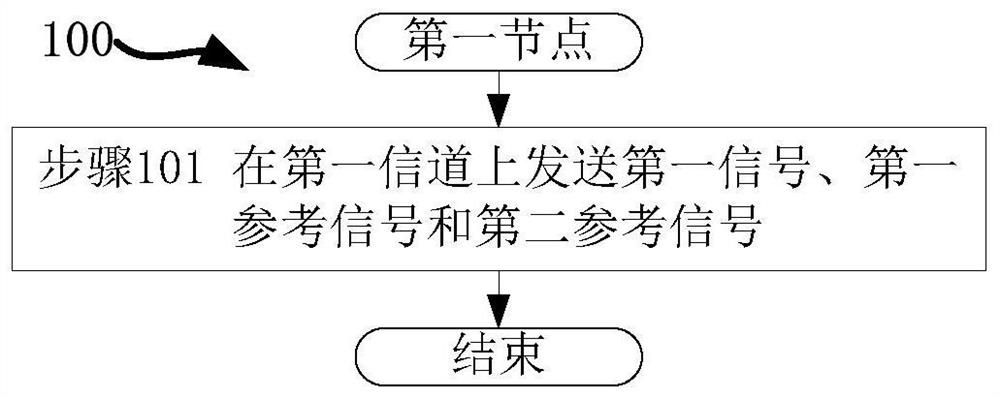
[0077] Embodiment 1 illustrates a processing flowchart of a first node, as attached figure 1 shown. in the attached figure 1 In the shown 100, each box represents a step. In Embodiment 1, the first node in this application sends a first signal, a first reference signal and a second reference signal on a first channel in step 101 .

[0078] In Embodiment 1, the small-scale fading channel parameters experienced by the second reference signal are used to infer the small-scale fading channel parameters experienced by the first signal; the first reference signal is associated with the second At least one antenna port of the reference signal, a first modulation and coding method is used to determine the density of the first reference signal in the time domain, the first modulation and coding method is different from the modulation and coding method of the first signal.

[0079] As an embodiment, the physical layer channel carrying the first signal includes a PUSCH (Physical Uplin...

Embodiment 2

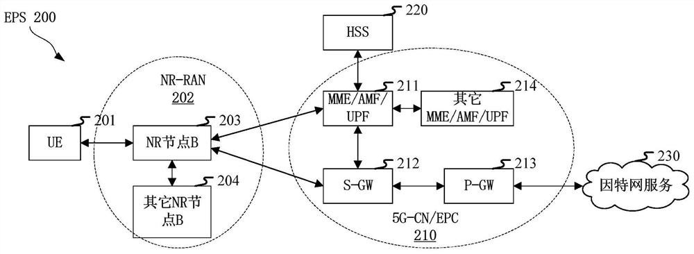
[0127] Embodiment 2 illustrates the schematic diagram of network architecture, as attached figure 2 shown.

[0128] figure 2A diagram illustrating a network architecture 200 of 5G NR, LTE (Long-Term Evolution, long-term evolution) and LTE-A (Long-Term Evolution Advanced, enhanced long-term evolution) systems. The 5G NR or LTE network architecture 200 may be called EPS (Evolved Packet System, Evolved Packet System) 200 by some other suitable term. EPS 200 may include one or more UE (User Equipment, User Equipment) 201, NG-RAN (Next Generation Radio Access Network) 202, EPC (Evolved Packet Core, Evolved Packet Core) / 5G-CN (5G-Core Network , 5G core network) 210, HSS (Home Subscriber Server, home subscriber server) 220 and Internet service 230. The EPS may be interconnected with other access networks, but these entities / interfaces are not shown for simplicity. As shown, the EPS provides packet-switched services, however those skilled in the art will readily appreciate that ...

Embodiment 3

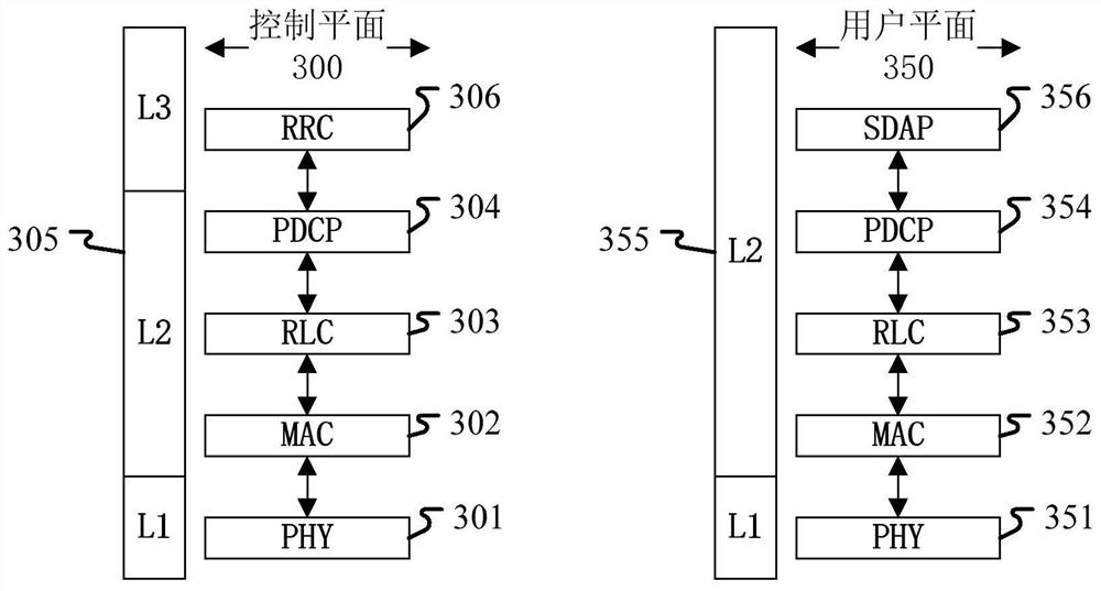
[0146] Embodiment 3 shows a schematic diagram of an embodiment of a wireless protocol architecture of a user plane and a control plane according to the present application, as shown in the attached image 3 shown. image 3 is a schematic diagram illustrating an embodiment of a radio protocol architecture for a user plane 350 and a control plane 300, image 3 The radio protocol architecture for the control plane 300 between the first communication node device (UE, gNB or RSU in V2X) and the second communication node device (gNB, UE or RSU in V2X) is shown in three layers: layers 1. Layer 2 and Layer 3. Layer 1 (L1 layer) is the lowest layer and implements various PHY (Physical Layer) signal processing functions. The L1 layer will be referred to herein as PHY 301 . A layer 2 (L2 layer) 305 is above the PHY 301 and is responsible for a link between the first communication node device and the second communication node device through the PHY 301 . The L2 layer 305 includes a MA...


PUM


Abstract

The invention discloses a method and an apparatus in a node used for wireless communication. The node sends a first signal, a first reference signal and a second reference signal on a first channel; the small-scale fading channel parameter experienced by the second reference signal is used for deducing the small-scale fading channel parameter experienced by the first signal; the first reference signal is associated to at least one antenna port of the second reference signal, a first modulation coding scheme is used for determining the density of the first reference signal in a time domain, and the first modulation coding scheme is different from a modulation coding scheme of the first signal. According to the method and the device, the reference modulation coding mode of the phase tracking reference signal during resource mapping is decorrelated with the modulation coding mode adopted by the data, so that the mapping of the uplink transmission phase tracking reference signal based on non-scheduling is more easily obtained by the base station side, and the overall performance of the system is further improved.

Description

technical field [0001] The present application relates to a transmission method and device in a wireless communication system, in particular to a transmission scheme and device related to multiple antennas in wireless communication. Background technique [0002] The application scenarios of future wireless communication systems are becoming more and more diversified, and different application scenarios put forward different performance requirements for the system. In order to meet the different performance requirements of various application scenarios, the new air interface technology (NR, New Radio) (or Fifth Generation, 5G) to conduct research, passed the WI (Work Item, work item) of NR at the 3GPP RAN#75 plenary session, and started to standardize NR. [0003] A key technology of NR is to support beam-based signal transmission, and its main application scenario is to enhance the coverage of NR devices working in millimeter wave frequency bands (such as frequency bands gr...

Claims


Application Information

Patent Timeline
IPC IPC(8): H04L5/00H04L1/00H04W72/12
CPCH04L5/003H04L1/0003H04W72/1263H04L1/0009H04L1/0023H04L1/18H04L5/0048H04L5/0023H04L5/0094H04W72/21H04L5/0051H04W72/0446H04W72/0453
Inventor 蒋琦张晓博
Owner SHANGHAI LANGBO COMM TECH CO LTD
Why Eureka
Try Eureka