Side edge rubber buckling chain belt

A tape and plastic chain technology, applied in the field of machinery, can solve the problems of easy falling off of leak-proof strips, tape deviation and tearing, complex casting cost, etc., to increase power consumption and layout space, improve tear resistance and tensile strength, The effect of saving facility investment

Pending Publication Date: 2022-02-01
刘素华
View PDF0 Cites 0 Cited by
  • Summary
  • Abstract
  • Description
  • Claims
  • Application Information

AI Technical Summary

Problems solved by technology

[0002] At present, there are armor-belt type, belt-type, and strip-piercing conveyor belts. The armor-belt type uses multi-section chains to connect the steel shafts of the armor-piercing pieces from both sides of the armor belt. A leak-proof strip is set between the nail and the nail. Because the leak-proof strip is easy to fall off, it often causes material leakage. The gap between the nail and the nail is very serious. In order to make the nail rotate around the drum, the nail is made short. , the casting is complicated and the cost is high, and the small nails are pierced into a nail belt. The manufacturing process of piercing the nails is complicated, and the waste of materials and labor is serious. In order to prevent leakage, the nails are covered with tape. When the drum rotates, the butt seam between the nail pieces bulges, and the middle part of the nail piece is sunken, so that the attached tape is lifted off by the raised nail piece, and there is a gap between the lifted and fallen off tape and the nail belt, and the nail belt rotates the tape If the belt does not rotate with the armor belt, the belt will be torn off by the resistance of the material, which will further increase the cost of use, cause the site to stop production, and the maintenance workload will be heavy. The large amount often causes the position of the driving pulley and the driven pulley to be adjusted to match the tension of the belt in order to continue working. Because the pulleys at both ends of the belt need to be pulled too far away on site, the belt load is too large and the belt is over-tensioned, which leads to the breakage of the belt. Serious production stoppage accidents are caused, and the motor power is often overloaded when the motor starts to rotate the belt due to excessive te...

Method used


Image

  • Side edge rubber buckling chain belt
  • Side edge rubber buckling chain belt
  • Side edge rubber buckling chain belt

Examples


Embodiment 1

[0216]1-buckle side rubber chain belt, 2-conveyor belt, 3-drive chain, 4-chain connecting conveyor belt parts, 5-fixed link shaft tape, 6-fixed ring chain tape, 7-roller chain, 8- Ring chain, 9-buckle sprocket shaft, 10-fixed buckle sprocket shaft, 11-ring chain, 12-side shaft rubber chain belt, 13-fixed chain link shaft through hole, 14-fixed chain link shaft blind hole, 15-Fixed chain link shaft seam edge, 16-Fixed chain link shaft buckle edge, 17-Fixed chain link shaft bonding edge, 18-Fixed chain link shaft nut, 19-Fixed chain link shaft warp and weft cloth, 20-Fixed chain Knuckle shaft side overlapping belt, 21-steep turn guide wheel, 22-ring chain buckle, 23-buckle connection ring chain structure, 24 side ring chain tape, 25-side buckle belt, 26-fixed chain link Shaft and screw parts, 27 connecting ring chain through hole, 28-nut, 29-screw rod, 30-screw, 31-folding belt, 32-bucket plate, 33-square buckle plate, 34-circular buckle plate, 35 -Chain piece, 36-Double hole c...

specific Embodiment approach

[0217] Example 1

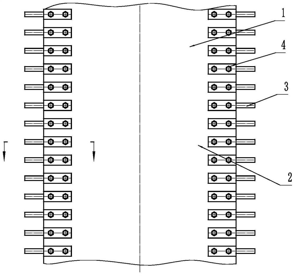
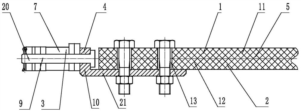
[0218] like Figure 1 to Figure 2 As shown, the buckle side rubber chain belt 1 includes a conveyor belt 2, a drive chain 3 and a chain connecting conveyor belt piece 4, the conveyor belt 2 includes a fixed link shaft tape 5, and the drive chain 3 includes a roller chain 7, and the roller chain 7 Including buckle sprocket shaft 9, chain connection conveyor belt part 4 includes fixed buckle sprocket shaft part 10, fixed buckle sprocket shaft part 10 connects buckle sprocket shaft 9 and fixed chain link shaft tape 5 to form side shaft rubber chain belt 12, fixed buckle The sprocket shaft part 10 and the buckle sprocket shaft 9 are integrated, and the side of the fixed chain link shaft tape 5 is provided with a fixed chain link shaft through hole 13. When using the fixed chain link shaft through hole 13, the fixed buckle sprocket shaft part 10 will buckle The sprocket shaft 9 is fixed on both sides of the fixed chain link shaft adhesive tape 5, and the fixed c...

Embodiment 2

[0224] like Figure 12 As shown, when the fixed chain link shaft nut 18 is used, the fixed chain link shaft nut 18 is arranged on the side of the fixed chain link shaft tape 5, and the fixed chain link shaft screw member 26 is set on the drive chain 3, so that the fixed chain link shaft screw Part 26 fixes the sprocket shaft 9 on both sides of the fixed chain link shaft adhesive tape 5, and the fixed chain link shaft screw part 26 is connected with the chain sprocket shaft 9 splits.

[0225] It is also possible to fix the sprocket shaft 9 on one side of the fixed chain link shaft tape 5 by the fixed chain link shaft screw member 26 .

[0226] can also be as Figure 13 As shown, the fixed chain link shaft screw member 26 is integrated with the chain wheel shaft 9 .

[0227] Others are with embodiment 1.


PUM


Abstract

The invention belongs to the field of machinery, and particularly relates to a side edge rubber buckling chain belt. The side edge rubber buckling chain belt comprises a conveying belt, a driving chain and a chain connecting conveying belt piece, the conveying belt comprises a fixed chain link shaft rubber belt or a fixed annular chain rubber belt, the driving chain comprises a roller chain or an annular chain, the roller chain comprises a chain buckling wheel shaft, the chain connecting conveying belt piece comprises a fixed buckle chain wheel shaft piece or a connecting annular chain piece, the fixed buckle chain wheel shaft piece connects a buckle chain wheel shaft and a fixed chain link shaft adhesive tape to form a side edge shaft belt, the fixed buckle chain wheel shaft piece and the buckle chain wheel shaft are connected in a split mode or in an integrated mode, the side edge of the fixed chain link shaft adhesive tape is provided with a fixed chain link shaft through hole, or a fixed chain link shaft sewing edge, or a fixed chain link shaft buckling edge, or a fixed chain link shaft side edge folding belt, or a fixed chain link shaft side edge steel wire belt, or a fixed chain link shaft side edge strong adhesive tape, or a fixed chain link shaft zipper, the buckle chain wheel shaft comprises a buckle chain wheel rack and a side edge belt buckling piece, and the buckle chain wheel rack and the side edge belt buckling piece are connected in a split or integrated mode.

Description

technical field [0001] The invention belongs to the field of machinery, and in particular relates to a buckle side rubber chain belt. Background technique [0002] At present, there are armor-belt type, belt-type, and strip-piercing conveyor belts. The armor-belt type uses multi-section chains to connect the steel shafts of the armor-piercing pieces from both sides of the armor belt. A leak-proof strip is set between the nail and the nail. Because the leak-proof strip is easy to fall off, it often causes material leakage. The gap between the nail and the nail is very serious. In order to make the nail rotate around the drum, the nail is made short. , the casting is complicated and the cost is high, and the small nails are pierced into a nail belt. The manufacturing process of piercing the nails is complicated, and the waste of materials and labor is serious. In order to prevent leakage, the nails are covered with tape. When the drum rotates, the butt seam between the nail p...

Claims


Application Information

Patent Timeline
IPC IPC(8): B65G15/30B65G15/56B65G15/60B65G17/02
CPCB65G17/02B65G15/40B65G15/08B65G15/36B65G15/30B65G15/56B65G17/30B65G15/34B65G23/02B65G17/38B65G23/06B65G15/32B65G17/06B65G23/32B65G15/14B65G17/40
Inventor 刘素华
Owner 刘素华
Why Eureka
Try Eureka