CT imaging system and imaging method

A CT imaging and subsystem technology, applied in the field of radiation imaging, can solve the problems of a large number of radiation sources and detectors, and achieve the effect of ensuring the scanning effect, increasing the scanning speed, and improving the quality of the reconstructed image

Pending Publication Date: 2022-04-05
BEIJING HANGXING MACHINERY MFG CO LTD
View PDF7 Cites 2 Cited by
  • Summary
  • Abstract
  • Description
  • Claims
  • Application Information

AI Technical Summary

Problems solved by technology

[0006] In view of the above analysis, the present invention aims to provide a CT imaging system and imaging method to solve the problem that a large number of radiation sources and detectors are required in the existing CT system using static CT equipment

Method used


Image

  • CT imaging system and imaging method
  • CT imaging system and imaging method
  • CT imaging system and imaging method

Examples


Embodiment 1

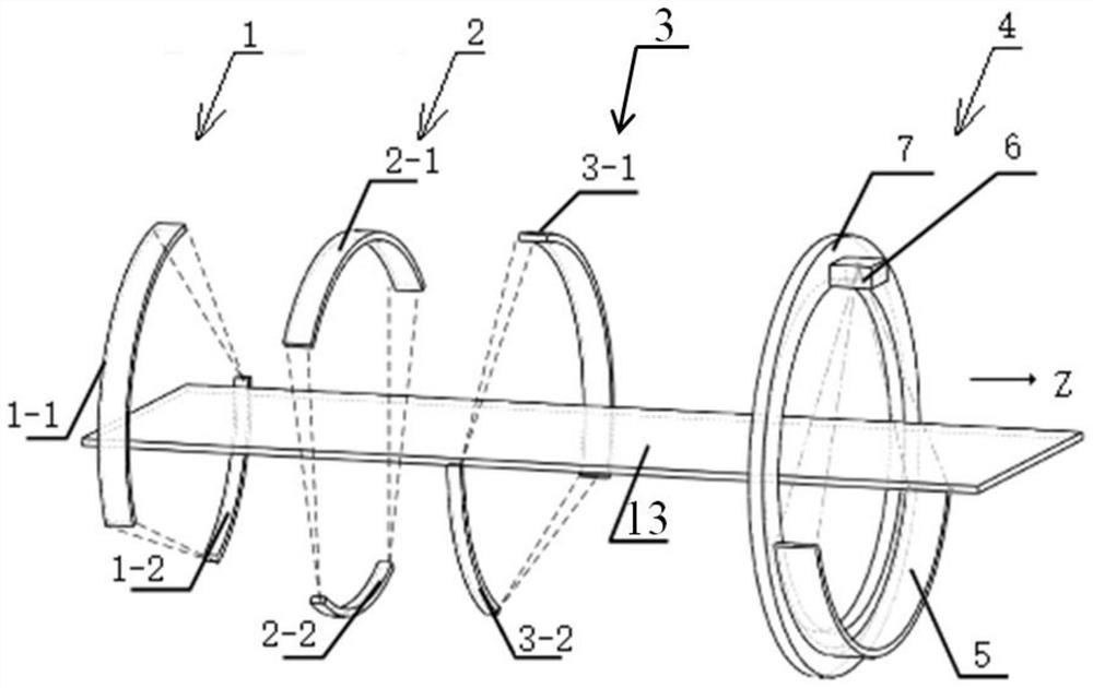
[0045] A specific embodiment of the present invention discloses a CT imaging system, comprising: an object conveying component, an object inlet and outlet, a static imaging subsystem, a dynamic imaging subsystem and a rack, the static imaging subsystem and the dynamic imaging subsystem The subsystems are all fixed on the frame, and the static imaging subsystem includes multiple groups of static imaging units fixedly arranged.

[0046] The CT imaging system in the present invention is mainly used in CT equipment for scanning moving objects. The CT imaging system includes a static imaging subsystem and a dynamic imaging subsystem.

[0047]The CT equipment includes a CT imaging system and an object conveying part of a common CT system. The object travels on the conveying channel formed by the conveying part and scans during the traveling process. The object conveying components include the moving motor and conveyor belt in the security CT, or the moving motor and CT scanning bed ...

Embodiment 2

[0060] see figure 1 , as a specific implementation manner, this embodiment adopts an arrangement in which the dynamic imaging subsystem is located downstream of the static imaging subsystem. A static imaging subsystem and a dynamic imaging subsystem are sequentially arranged along the conveying direction of the object on the conveying channel, and the fusion of static scanning and dynamic scanning of the object is realized through the two sets of static and dynamic imaging subsystems. The static imaging subsystem and the dynamic imaging subsystem are arranged along the direction of the conveying channel, and the object passes through the channel relying on the conveying components, and the entire scanning process is completed after data collection by each imaging subsystem.

[0061] In this embodiment, the object is first statically scanned by the static imaging subsystem, and then dynamically scanned by the dynamic imaging subsystem disposed downstream of the static imaging s...

Embodiment 3

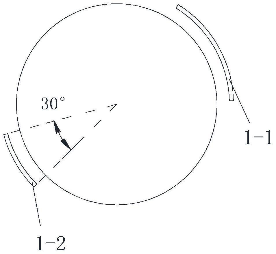
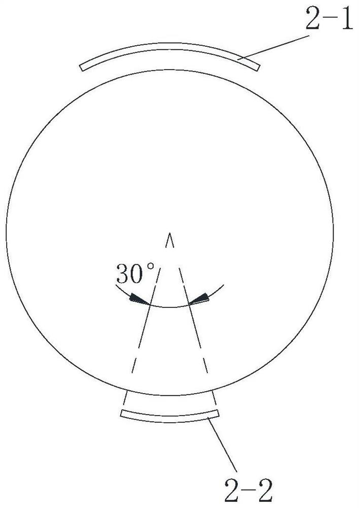
[0079] In another embodiment of the present invention, the static imaging unit of Embodiment 1 is adopted, and each group of static imaging units includes dispersedly arranged multi-focus radiation sources 50 and detector assemblies 20, and the distributed radiation sources include a plurality of radiation source focal points 101, The radiation source is preferably a carbon nanotube-based cold-cathode X-ray tube or a grid-controlled hot-cathode X-ray tube. The ray source focal points 101 in each group of static imaging units are distributed on one or more planes along the conveying channel, and can be arranged as straight lines or arcs, and the adjacent focal points can be arranged at equal or non-equal intervals The form of layout. The arrangement of distributed multi-focus ray sources corresponding to different static imaging units can be in the same arrangement form, or can be a combination of different forms. In addition, each ray source can set tube voltage, high and low ...


PUM

PropertyMeasurementUnit
thicknessaaaaaaaaaa
depthaaaaaaaaaa

Abstract

The invention relates to a CT imaging system and an imaging method, belongs to the technical field of radiation imaging, and solves the problem that an existing CT system adopting static CT equipment needs a large number of radiation sources and detectors. The CT imaging system comprises a static imaging subsystem, a dynamic imaging subsystem and a rack, the static imaging subsystem and the dynamic imaging subsystem are both fixed to the rack, and the static imaging subsystem comprises multiple sets of static imaging units which are fixedly arranged. By fusing the static imaging subsystem and the dynamic imaging subsystem, the arrangement number of ray sources and detectors in static CT can be reduced, relatively complete projection data can be obtained in a data fusion mode, the quality of reconstructed images is improved, and relatively complete and ideal overall reconstruction results are obtained.

Description

technical field [0001] The invention relates to the technical field of radiation imaging, in particular to a CT imaging system and an imaging method. Background technique [0002] Among the X-ray-based explosives inspection technologies, X-ray computed tomography imaging technology (referred to as "CT technology") is highly valued in the field of security inspection due to its own unique advantages. [0003] The current security inspection CT equipment is mainly divided into spiral CT and static CT equipment based on slip ring technology. Spiral CT equipment usually arranges the radiation source and detector on the rotating frame, and solves the problem of continuous rotation of the frame through slip ring technology. Since the centrifugal force experienced by the part increases with the square of the rotation speed, the increase in scanning speed places high demands on the performance of the frame. In addition, the angle accuracy and position accuracy of the gantry during...

Claims


Application Information

Patent Timeline
Patent Type & Authority Applications(China)
IPC IPC(8): G01N23/046G01V5/00
Inventor 李保磊魏增辉孙翠丽莫阳牛素鋆徐圆飞
Owner BEIJING HANGXING MACHINERY MFG CO LTD
Why Eureka
Try Eureka