Scroll-type compressor

A technology of scroll compressors and compression chambers, applied in the direction of rotary piston machines, rotary piston pumps, mechanical equipment, etc., can solve problems such as unequal flows

Inactive Publication Date: 2004-11-24
CARRIER CORP
View PDF0 Cites 0 Cited by
  • Summary
  • Abstract
  • Description
  • Claims
  • Application Information

AI Technical Summary

Problems solved by technology

[0009] There may also be unequal flows due to the

Method used


Image

  • Scroll-type compressor
  • Scroll-type compressor
  • Scroll-type compressor

Examples


Embodiment Construction

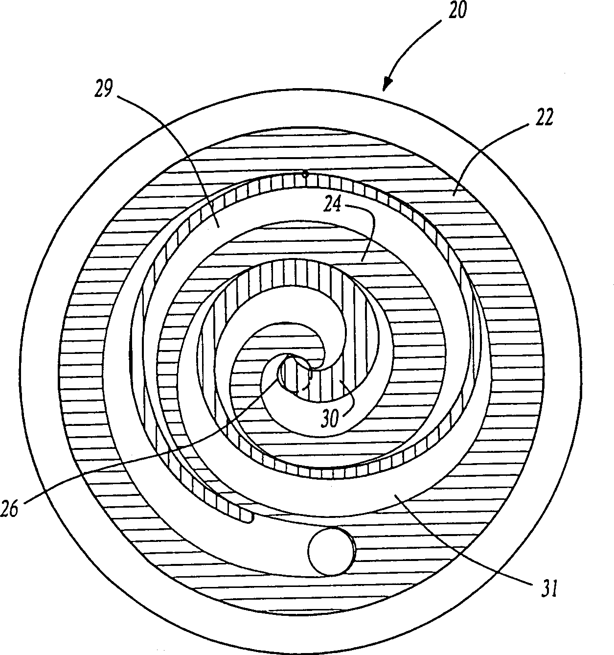
[0026] Figure 1A A prior art scroll compressor pump unit 20 having a non-rotating scroll member 22 with a scroll 24 is shown. As shown, scroll 24 begins at a generally central point 6 and extends generally along a helical line to an outer location. As also shown, orbiting scroll 30 cooperates with scroll 24 and defines a plurality of compression chambers such as 29 and 31 .

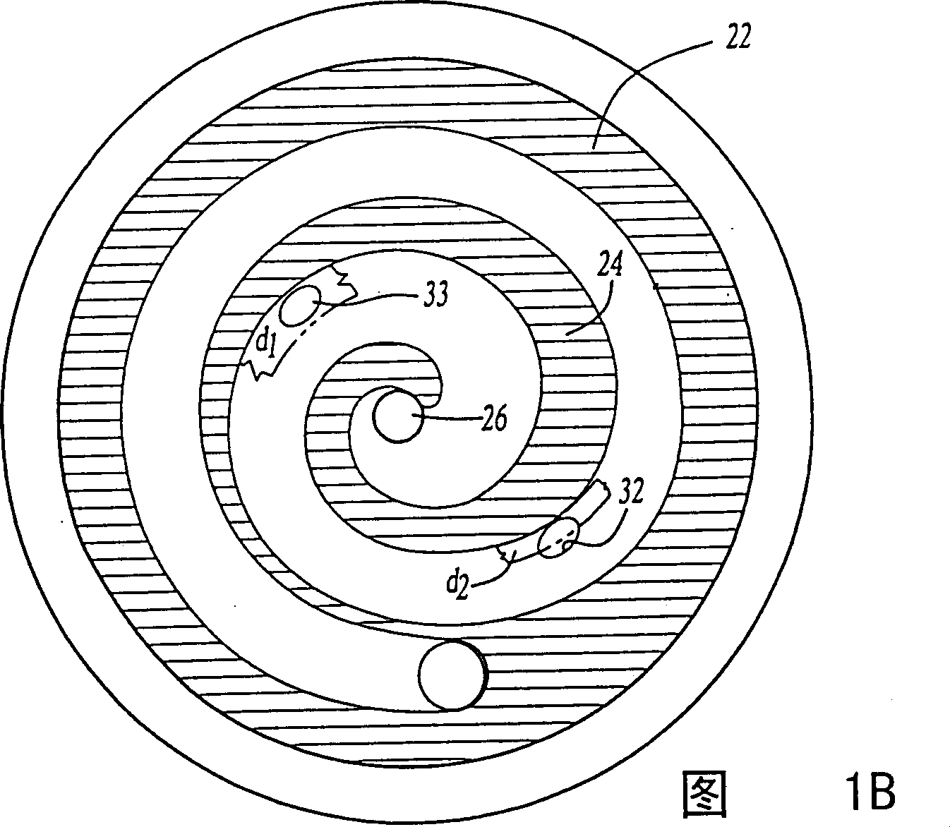
[0027] As shown in FIG. 1B , injection ports 33 and 32 selectively communicate with compression chambers 31 and 29 , respectively.

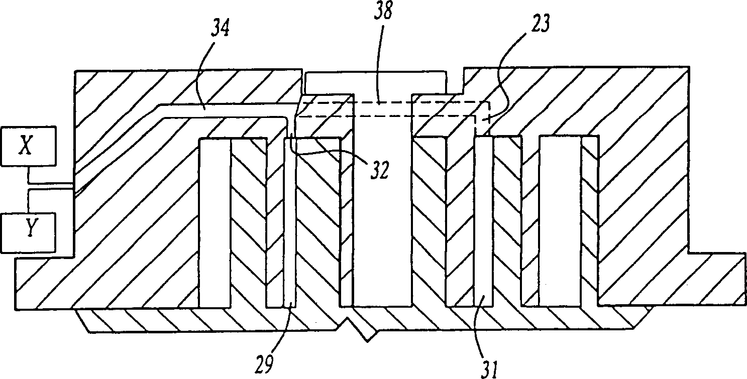
[0028] Such as figure 2 As shown, passage 34 communicates with injection port 32 . The passage 34 communicates with the injection port 33 through a passage 38 . Channel 38 is often curved to avoid interference with the discharge opening. For this reason, the channel is shown with dashed lines. Passage 34 communicates within an economizer cycle (x) or with an unloader valve (y) or both, as schematically shown.

[0029] Depend on figure 2 It can be seen that the flui...


PUM


Abstract

Scroll compressors are provided with injection ports for injecting fluid from a supplemental source such as an economizer cycle or by-passing fluid through an unloader valve. The injection ports are formed in each of two compression chambers whose volume is being reduced towards a discharge port. Due to various design constraints, it is desirable that the injection ports have unequal characteristics. In some cases, it may be desirable to make the injection ports of different size, including width, depth, and length. In other applications, it may be desirable to locate the injection ports at different angular positions relative to compression chambers seal off from suction.

Description

[0001] This application claims priority to US Patent Provisional Application No. 60 / 096,722, filed August 17,1998. technical field [0002] The present invention relates to scroll compressors and, in particular, to optimization of the size and / or position of injection ports of scroll compressors. Background technique [0003] Scroll compressors are widely used in the field of refrigeration compression. Scroll compressors generally include an orbiting scroll member and a non-orbiting scroll member. Both scroll members have helical wraps extending from their respective base plates. The helical wraps of the orbiting scroll member and the non-orbiting scroll member cooperate to define compression pockets. Typically, at least two compression chambers are moved simultaneously toward a discharge port to compress the refrigerant. [0004] The economizer cycle is a compressor feature that has been used in scroll compressors and increases the efficiency of the overall refrigeration...

Claims


Application Information

Patent Timeline
IPC IPC(8): F04C18/02F04C29/00F04C29/04
CPCF04C29/0035F04C29/042F04C18/02
Inventor 亚历山大·利夫森詹姆斯W·布什
Owner CARRIER CORP
Why Eureka
Try Eureka