Thermal-response switch

A thermal response and switching technology, which is applied to thermal switches, electrical switches, thermal switch components, etc., can solve the problem that the bimetal suction fixture 51 and the laser irradiation device 52 cannot be arranged in the same position, and the position of the bimetal strip is offset. It can solve the problems of shifting, can not be manufactured cheaply, etc., to achieve the effect of simple assembly process, stable welding depth, and stable joint strength.

Inactive Publication Date: 2005-01-12
ALPS ALPINE CO LTD
View PDF0 Cites 0 Cited by
  • Summary
  • Abstract
  • Description
  • Claims
  • Application Information

AI Technical Summary

Problems solved by technology

[0010] Since in the manufacture of the above-mentioned conventional thermal response switch, when the fixed terminal and the bimetal are laser-welded, the metal will scatter when the metal is molten, and the scatter metal will remain at the bottom of the housing. If it is removed, another process such as cleaning is required, so assembly becomes complicated, and there is a problem that it cannot be manufactured at low cost.
[0011] In addition, in accordance with the miniaturization of the switch case, the bimetal suction jig 51 and the laser irradiation device 52 could not be arranged at the same position without interfering with each other in the conventional thermal reaction switch assembly.
Therefore, after the bimetal is installed in the housing, the workpiece must be transported to the location of the laser irradiation device 52 in the direction of the arrow Y, and the position of the bimetal may be caused by this movement.

Method used


Image

  • Thermal-response switch
  • Thermal-response switch
  • Thermal-response switch

Examples


Embodiment Construction

[0034] Below, the embodiment of the present invention is described with reference to accompanying drawing,

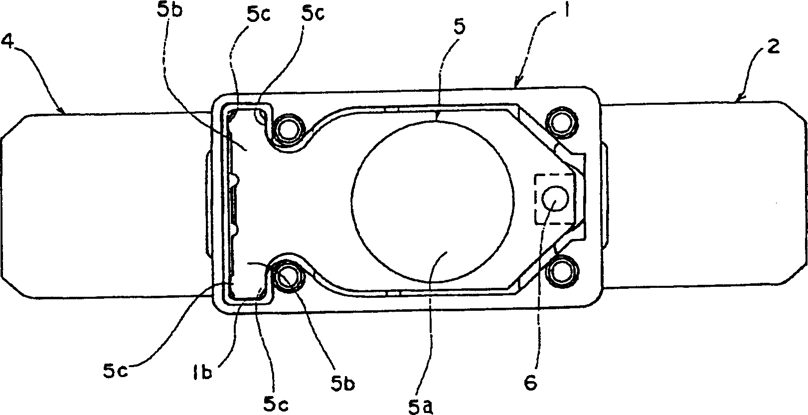
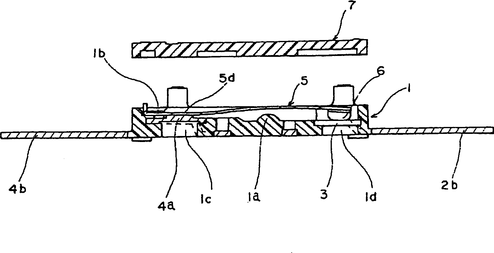
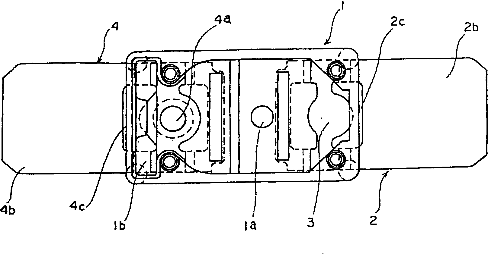
[0035] under, Figure 1 to Figure 9 Examples of the present invention are shown. figure 1 It is a top view with the thermal response switch cover removed. figure 2 yes means figure 1 A cross-sectional view of the thermally reactive switch shown with the cover removed. image 3 yes means figure 1 A top view of the housing with the fixed contacts and fixed terminals of the thermally reactive switch shown with the cover removed. Figure 4 yes means figure 1 It is a sectional view of the housing with the fixed contacts and the fixed terminals in the state where the cover is removed of the shown thermal response switch. Figure 5 yes means figure 1 The bottom view of the housing with the fixed contacts and fixed terminals of the shown thermal response switch with the cover removed. Image 6 yes means figure 1 Top view of the bimetal strip with the movable con...


PUM


Abstract

The purpose of the present invention is to provide a structure of a thermal-response switch using a bimetal piece, which is capable of preventing the scattering of melted metal when incorporating the bimetal piece into the housing and laser-welding it on a fixed terminal and of incorporating the bimetal piece with high precision. To solve the problem, the thermal switch has a housing with a bottom, a fixed contact arranged on the inner bottom face of the housing and a flip part capable of flipping according to the temperature, and comprises the bimetal piece with a movable contact, which contacts and separates from the fixed contact, fixed at one end thereof, and a fixed terminal arranged on the inner bottom of the housing with the other end of the bimetal piece overlapped and fixed thereon in a cantilever. An opening, through which a laser beam can be emitted from the outer bottom of the housing, is formed on the bottom of the housing to match the overlapped position between the fixed terminal and the bimetal piece.

Description

technical field [0001] The invention relates to a heat response switch, in particular to a switch structure in which the movable contact is turned over by the thermal reaction of the bimetal sheet, thereby opening or closing the electrical contact. Background technique [0002] The thermal response switch is provided with a movable electrode and a fixed electrode, and is connected with the circuit of the electrical equipment to protect the electrical equipment. The above-mentioned movable electrode is a thermal reaction element (bimetal) that combines several metal sheets with different thermal expansion coefficients to make a movable piece; while the above-mentioned fixed electrode forms a normally closed contact circuit together with the movable electrode. [0003] That is to say, since the thermal response switch connected to the circuit of the electrical equipment is made like this, that is, when an excessive current flows through the electrical equipment, or when the am...

Claims


Application Information

Patent Timeline
IPC IPC(8): H01H11/00H01H37/52H01H37/54
CPCH01H2011/0087H01H2037/525H01H37/52
Inventor 长谷山敦
Owner ALPS ALPINE CO LTD
Why Eureka
Try Eureka