
Rolling material joint device and continuous hot-rolling equipment with said device
A technology for rolling materials and equipment, which is applied in the direction of lighting and heating equipment, metal rolling, metal rolling, etc., which can solve the problem of longer overall length of equipment, inability to ensure the thickness accuracy of the end of the plate width, and longer travel distance of the joining device And other issues
- Summary
- Abstract
- Description
- Claims
- Application Information
AI Technical Summary
Problems solved by technology
Method used
Image

Examples
Embodiment Construction
[0063] Hereinafter, embodiments of the present invention will be described with reference to the drawings. In addition, in each figure, the same symbol has the same meaning.
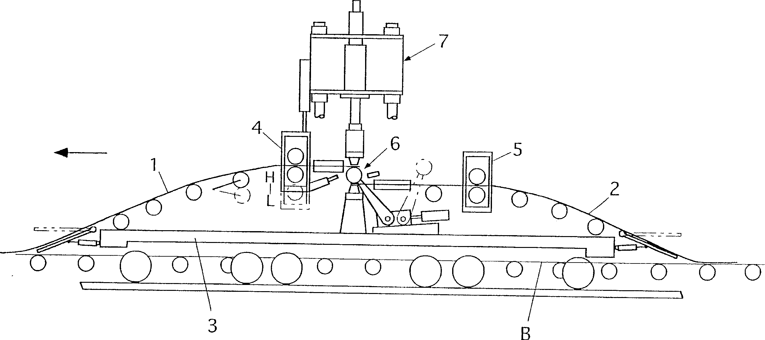
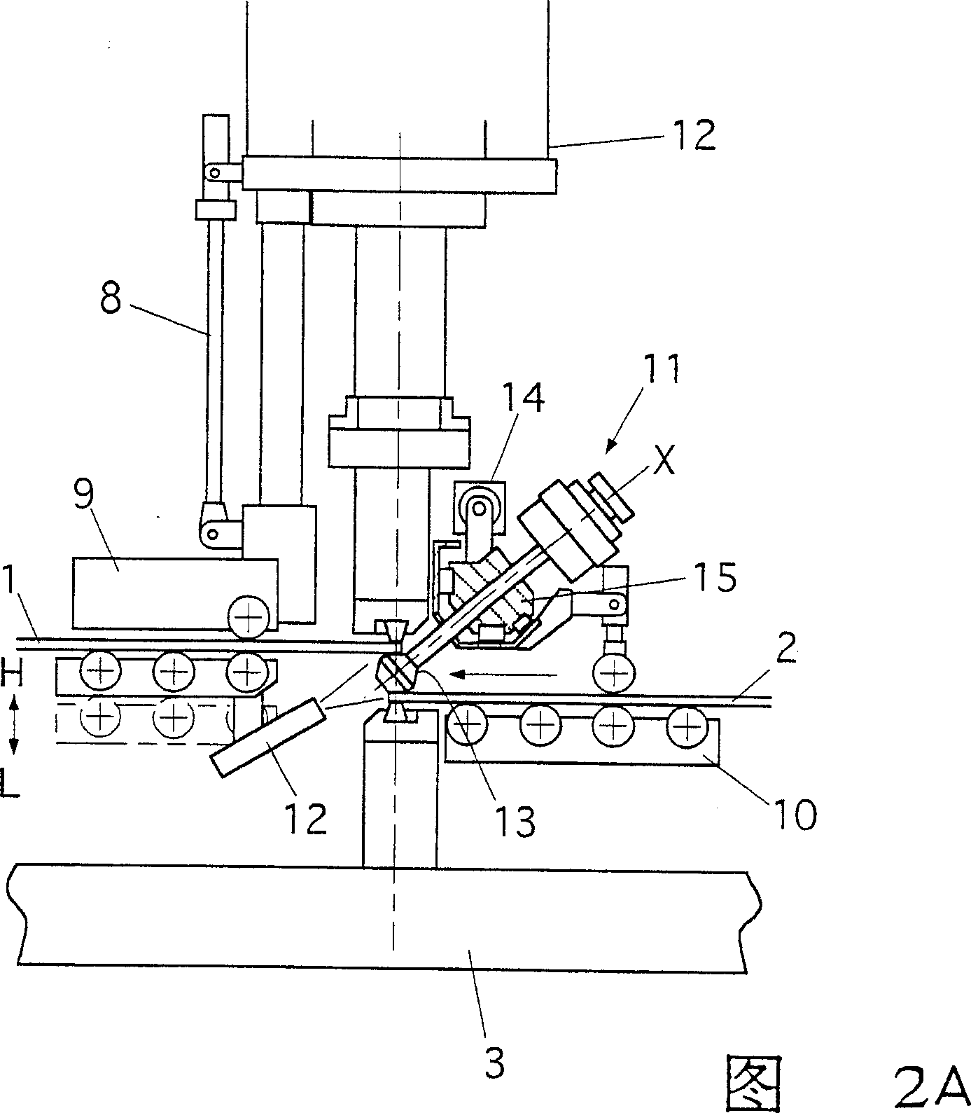
[0064] Figure 8 is a side view of the first embodiment of the present invention. In this figure, the rolling material joining device 20 of the present invention includes a trolley 22 that travels along the rolling direction shown by the arrow; Lifting rear end pinch roll 24; the front end pinch roll 26 that is installed on the trolley 22 and horizontally clamps the front end of the rolling material 2 behind; The processing device 28 that cuts the upper surface of the front end portion of the material 2; the reduction flame furnaces 30a, 30b that keep the processed surface in a reduced state; A crimping device 32 for rejoining the rolled materials 1, 2 compressed to substantially the same thickness.
[0065] The above structure and figure 1 The conventional technique shown is the same. In the rolle...
PUM
 Abstract
Description
Claims
Application Information