RF front-end circuit

A radio frequency front-end and circuit technology, applied in electrical components, space transmit diversity, transmission systems, etc., can solve problems such as impedance matching difficulties, and achieve the effect of small insertion loss

Inactive Publication Date: 2004-06-23
FOXCONN (KUNSHAN) COMPUTER CONNECTOR CO LTD +1
View PDF0 Cites 20 Cited by
  • Summary
  • Abstract
  • Description
  • Claims
  • Application Information

AI Technical Summary

Problems solved by technology

But this will bring another problem: directly connecting the transmission path to the antenna will cause difficulties in impedance matching

Method used


Image

  • RF front-end circuit
  • RF front-end circuit
  • RF front-end circuit

Examples


Embodiment Construction

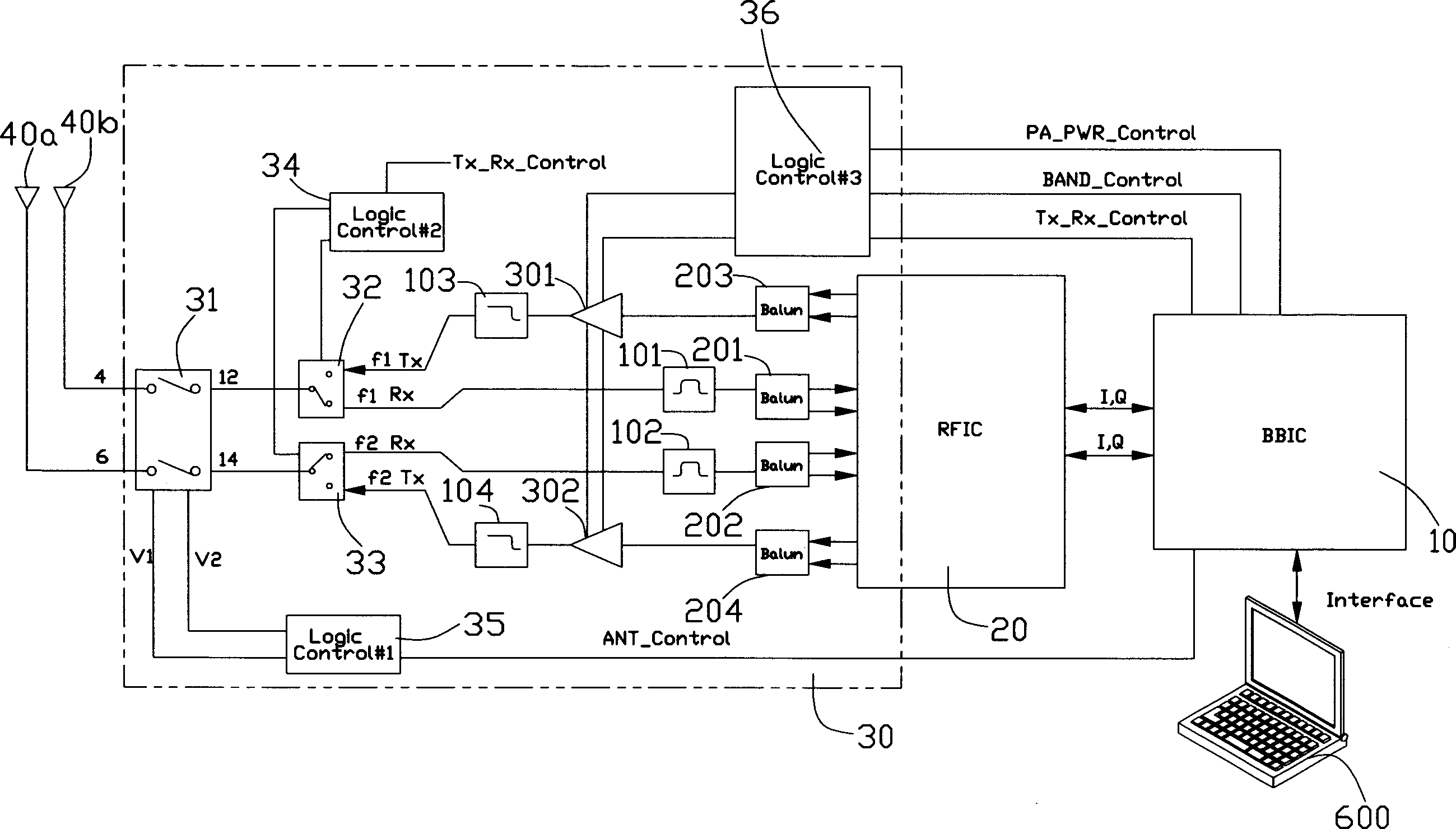
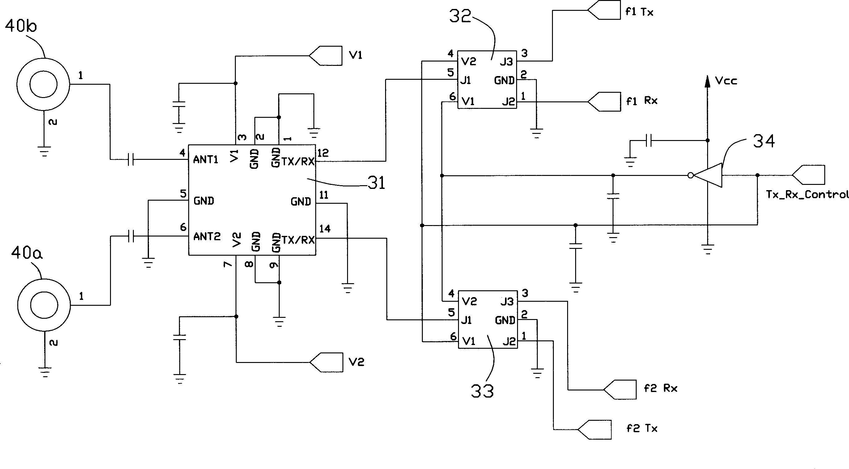
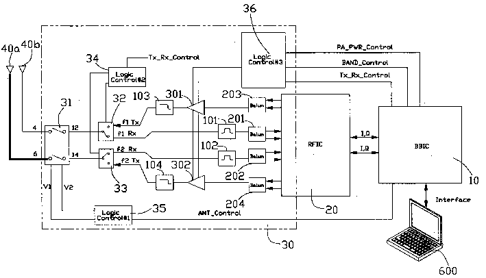
[0009] Please also see figure 1 and figure 2 As shown, the 802.11a / b dual-mode wireless local area network transceiver module includes a radio frequency part and a base frequency part. The radio frequency part includes first and second dual-frequency antennas 40a, 40b, a radio frequency front-end circuit 30 and a radio frequency integrated circuit 20 . The baseband part includes a baseband integrated circuit 10 , a radio frequency interface circuit (not labeled) and an interface circuit (not shown) connected to a notebook computer 600 .

[0010] The electrical coupling between the radio frequency integrated circuit 20 and the base frequency integrated circuit 10 can be realized by using the 802.11a / b chip adopted in the prior art. The electrical coupling between the baseband integrated circuit 10 and the interface circuit belongs to known technology, so it will not be repeated here.

[0011] The working frequency bands of the first and second dual-frequency antennas 40a an...


PUM


Abstract

The RF front-end circuit is used in the transceiver module for radio LAN and is connected to one first and one second double-frequency antennas. The RF front-end circuit includes the first and the second receiving paths for signals in different frequency bands, the first and the second transmitting paths for signals in different frequency bands, and switch unit to connect the first and the second receiving paths, the first and the second transmitting paths and the antennas. The switch unit includes double-pole double-throw switch and single-pole double-throw switch for the selective connection between the first and the second receiving paths, the first and the second transmitting paths and the first and the second double-frequency antennas.

Description

【Technical field】 [0001] The invention relates to a radio frequency front-end circuit, especially a radio frequency front-end circuit used in a dual-mode wireless transceiver module. 【Background technique】 [0002] With the development of wireless communication technology, more and more dual-mode wireless communication products, such as dual-mode mobile phones, dual-mode wireless LAN cards, etc., have begun to enter the wireless communication product market. [0003] The RF front-end circuit is the key point and difficulty in the design of the wireless transceiver module. Most of the purpose of RF front-end circuit design is to provide antenna diversity function. For wireless transceivers, the transmitted signal is usually much stronger than the received signal, so antenna diversity is more important for the receiver than for the transmitter. The design of most wireless transceivers only includes the antenna diversity design of the receiver, but not the antenna diversity d...

Claims


Application Information

Patent Timeline
Patent Type & Authority Applications(China)
IPC IPC(8): H01Q3/24H04B1/40H04B1/44H04B7/08
CPCH04B1/406H04B1/006H04B1/005H04B1/44
Inventor 合子明诺普康·亨瑞特彭平陈福生钱茵
Owner FOXCONN (KUNSHAN) COMPUTER CONNECTOR CO LTD
Why Eureka
Try Eureka