Optical semiconductor device

An encoder and optical technology, applied in the field of optical encoders, can solve the problems of reduced parallelism, narrowing of the distance between a light-emitting element 31 and a light-receiving element 32 and the like

Inactive Publication Date: 2004-11-03
KK TOSHIBA
View PDF1 Cites 6 Cited by
  • Summary
  • Abstract
  • Description
  • Claims
  • Application Information

AI Technical Summary

Problems solved by technology

This is because the distance between the light-emitting element 31 and the light-receiving element 32 is also reduced along with its miniaturization, and the parallelism of the light emitted from the light-emitting element 31 and incident on the light-receiving element 32 is reduced.

Method used


Image

  • Optical semiconductor device
  • Optical semiconductor device
  • Optical semiconductor device

Examples


Embodiment Construction

[0032] Hereinafter, embodiments of the present invention will be described with reference to the drawings.

[0033] (1) The first embodiment

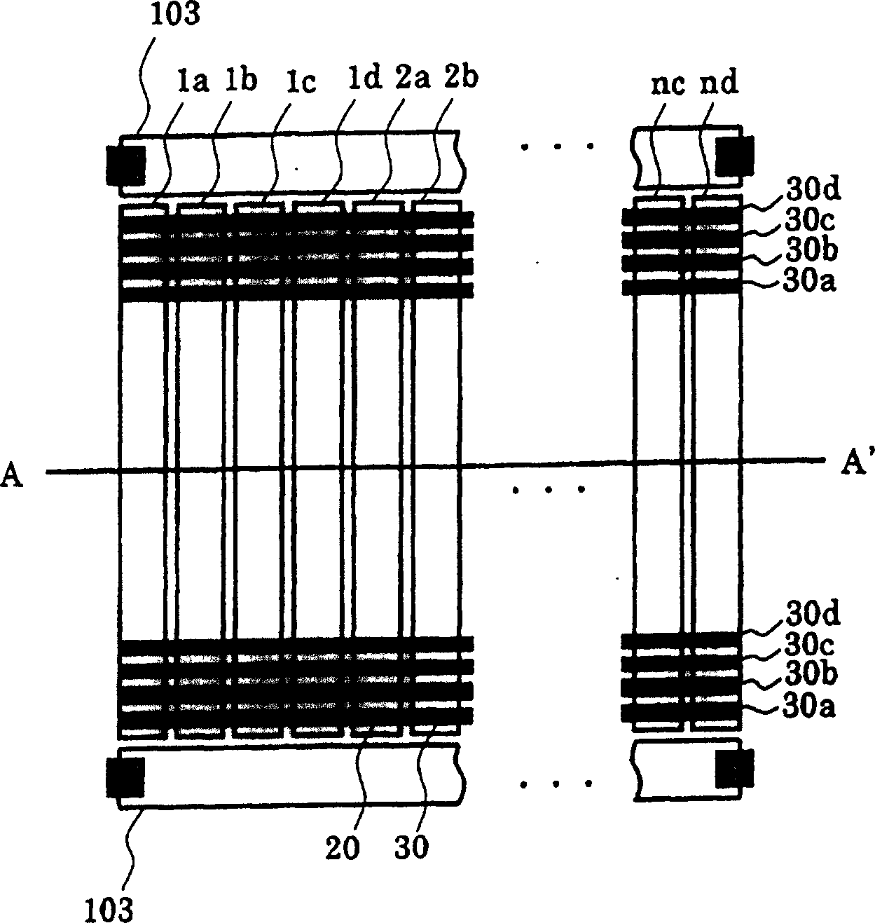
[0034] figure 1 It is a plan view showing an example of the photodiode configuration of the optical encoder according to the embodiment of the present invention.

[0035] That is, also in the present embodiment, substantially rectangular signal photodiodes (1a, 1b, . . . , nd) are arranged in parallel. These signal photodiodes are sequentially connected to any one of the four-phase wiring lines 30a to 30d. That is, four-phase photodiode groups (1a-na, 1b-nb, 1c-nc, 1d-nd) connected in common are formed by the four-phase wirings 30a-30d, respectively. Furthermore, adjacent photodiodes (for example, 1a to 1d) are arranged so as to belong to different photodiode groups.

[0036] In addition, above and below these photodiodes for signals, photodiodes 103 for DC cancellation are provided. The formation of the photodiodes 103 for DC can...


PUM


Abstract

An optical encoder comprises a plurality of first photodiodes, a second photodiode and a circuit. The plurality of first photodiodes are arranged in a first direction, each of the first photodiodes has a light detecting part extending along a direction substantially perpendicular to the first direction. The second photodiode is arranged near tips of the first photodiodes, and has a light detecting part extending along the first direction. The circuit performs a calculation based on outputs of the first and second photodiodes.

Description

technical field [0001] The present invention relates to optical encoders, and more particularly to optical encoders using photodiodes. Background technique [0002] An optical encoder is used as a position detection unit, and is used, for example, to detect the position of a print head of a printer or to control the amount of paper fed by a copier. [0003] Figure 11 It is a schematic diagram showing an example of the cross-sectional structure of main parts of an optical encoder. Right now, Figure 11 In the optical encoder shown in , the light-emitting element 31 and the light-receiving element 32 are arranged opposite to each other. For example, the light emitting element 31 has a structure in which an LED (light emitting diode: light emitting diode) 70 is mounted on the front end of a lead frame 40 and its periphery is appropriately molded with a resin. On the other hand, the light-receiving element 32 has a structure in which a light-receiving IC 80 is mounted on the ...

Claims


Application Information

Patent Timeline
IPC IPC(8): G01D5/347H01L31/10
CPCG01D5/34715
Inventor 田中明广铃永浩
Owner KK TOSHIBA
Why Eureka
Try Eureka