Apparatus for enlarging tube used in heat exchanger

A technology of heat exchanger tubes and heat exchangers, which is applied in the direction of heat exchange equipment, tubular elements, lighting and heating equipment, etc., can solve the problems of increased manufacturing costs and deteriorated transmission efficiency, and achieves increased productivity, improved transmission efficiency, and prevention of The effect of rail bending

CN1585678AInactive Publication Date: 2005-02-23KYOSHIN KOGYO CO LTD
0 Cites 5 Cited by

Patent Information

Authority / Receiving Office
CN · China
Patent Type
Applications(China)
Current Assignee / Owner
Publication Date
2005-02-23
Estimated Expiration
Not applicable · inactive patent

Smart Images

  • Figure 1
    Figure 1
  • Figure 2
    Figure 2
  • Figure 3
    Figure 3
Patent Text Reader

Abstract

A tube expander for heat exchangers is capable of organizing an ideal production line where the transportation efficiency is increased and the productivity is improved by having a transportation path in a straight line, that is, applying a method where the heat exchangers are carried into one end of the tube expander (in the left and right direction) and carried out from the opposite end, that is, the other end (so called through-the-center method). The left and right ends of the end plate 9 at the front side are inserted with a pair of first guide bars 10 , and the left and right ends at the back side are inserted with a pair of second guide bars 11 . A guide path 2a for a carrying device 23 or a guide path 2a to install a transportation device, in either case, the heat exchangers are transported from one end to the other of the base 2 , is established on the base 2 that supports the first guide bars 10 and the second guide bars 11 in a clearance between the first guide bars 10 and the ball screw 20.
Need to check novelty before this filing date? Find Prior Art

Description

technical field

[0001] The present invention relates to the expansion of a heat exchanger tube capable of manufacturing a heat exchanger by pressing a tube expanding mandrel for expanding the tube diameter into the tube, and integrating multi-layered cooling fins with a plurality of tubes passing through the cooling fins. diameter device. Background technique

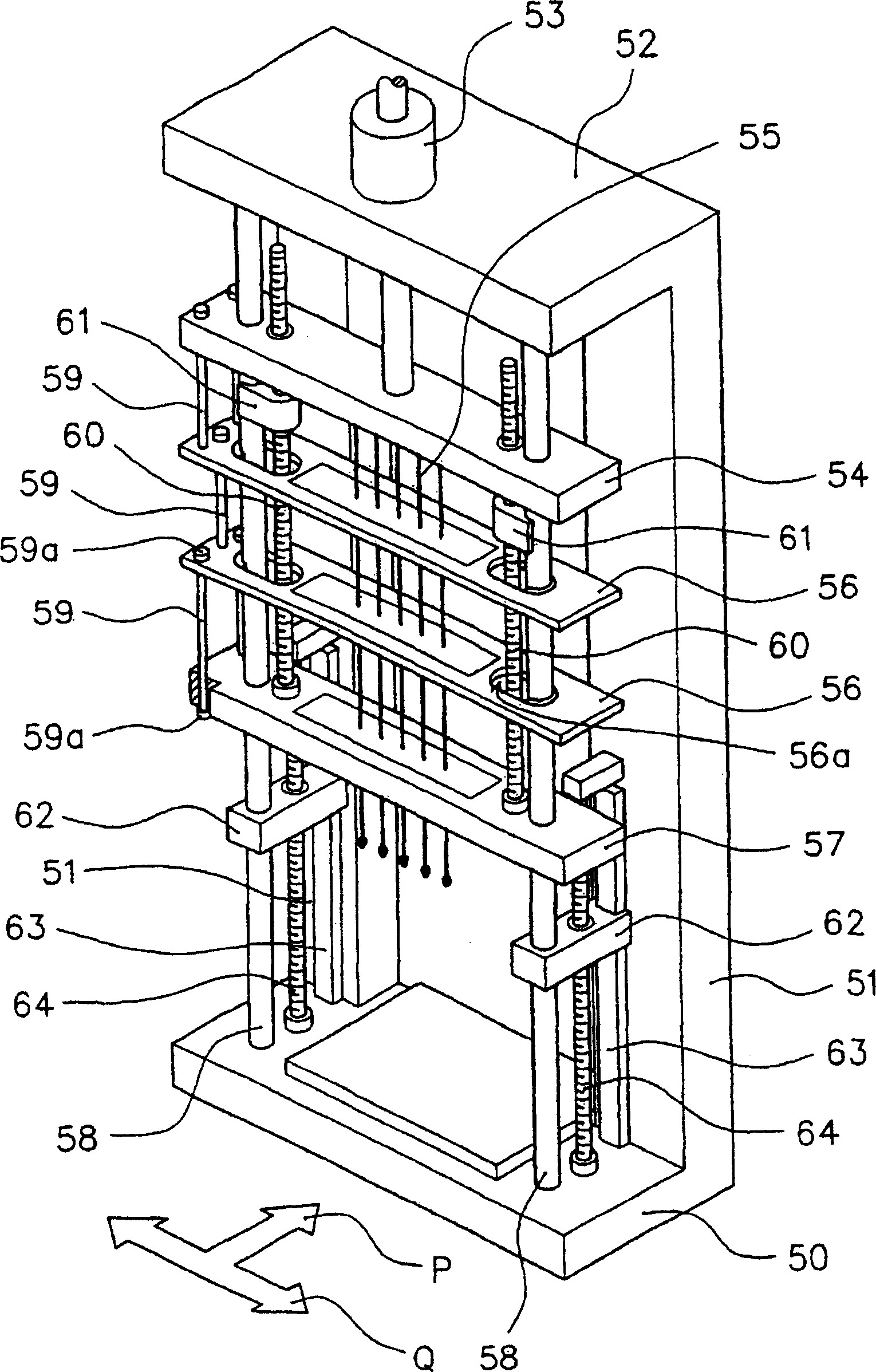
[0002] Now, the general structure of the expansion device of the tube for the heat exchanger, for example figure 2 As shown, a top 52 is erected across the upper ends of a pair of pillars 51, 51 provided on the base portion 50, and a working cylinder 53 is installed on the top 52 at the same time. A plurality of mandrels 55 for pipe expansion are arranged on the plate 54 .

[0003] Because the above-mentioned tube expansion mandrel 55 is to be suitable for the pipe diameter and tube length of the heat exchanger (not shown) positioned on the base portion 50 and is formed with a rod body with a small diameter and long...

Examples

Embodiment Construction

[0035] In order to explain the present invention in more detail, reference is made to the accompanying drawings.

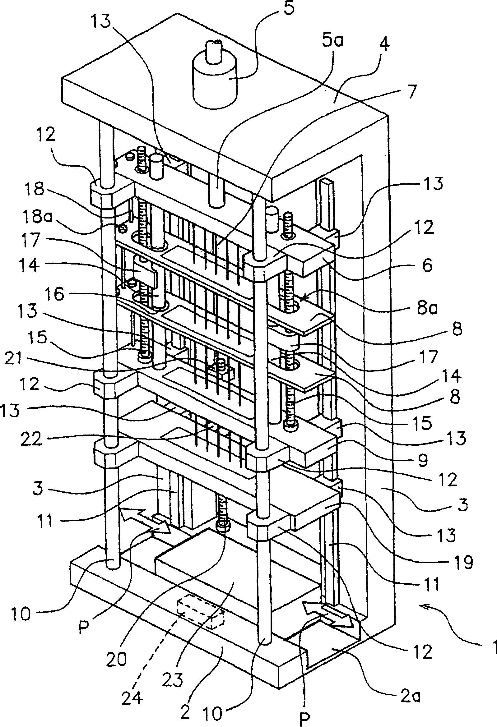
[0036] figure 1 Indicates the overall structure of the expanding device. The top 4 is erected across the upper ends of a pair of pillars 3 standing upward from the rear left and right positions of the base part 2 , and the device frame 1 is constituted by the base part 2 , the pillars 3 and the top 4 .

[0037] Further, a cylinder 5 having a cylinder rod 5 a that expands and contracts from the back of the top 4 toward the base 2 is attached to the top 4 .

[0038] The front end of the above-mentioned cylinder rod 5a is fixedly connected to the central part of the rectangular operating plate 6, and the operating plate 6 can be freely raised and lowered by the expansion and contraction of the cylinder rod 5a of the working cylinder 5.

[0039] In addition, a plurality of mandrels 7 for pipe expansion are vertically provided below the operation plate 6 , and the m...