Oil separator

An oil separator, a new type of technology, applied in the direction of refrigeration components, refrigerators, lighting and heating equipment, etc., can solve the problems of complex internal structure, large pressure loss, high material cost, etc., achieve simple internal structure, reduce manufacturing cost, speed big effect

Inactive Publication Date: 2006-05-03
LG ELECTRONICS (TIANJIN) APPLIANCES CO LTD
View PDF0 Cites 15 Cited by
  • Summary
  • Abstract
  • Description
  • Claims
  • Application Information

AI Technical Summary

Problems solved by technology

[0004] However, if figure 1 The oil separator shown has the following disadvantages: After the refrigerant with high flow velocity passes through the filler, the pressure loss is large, resulting in a large temperature difference between the air inlet and the air outlet, which affects the oil separation effect; the wall thickness of the tank body is 2.0mm, and the tank Two layers of filters are used inside, the internal structure is complex, the cost of materials is high, and it is not easy to produce; it is greatly affected by the frequency of the compressor, and when the frequency of the frequency conversion compressor increases, the oil return effect decreases

Method used


Image

  • Oil separator
  • Oil separator

Examples


Embodiment Construction

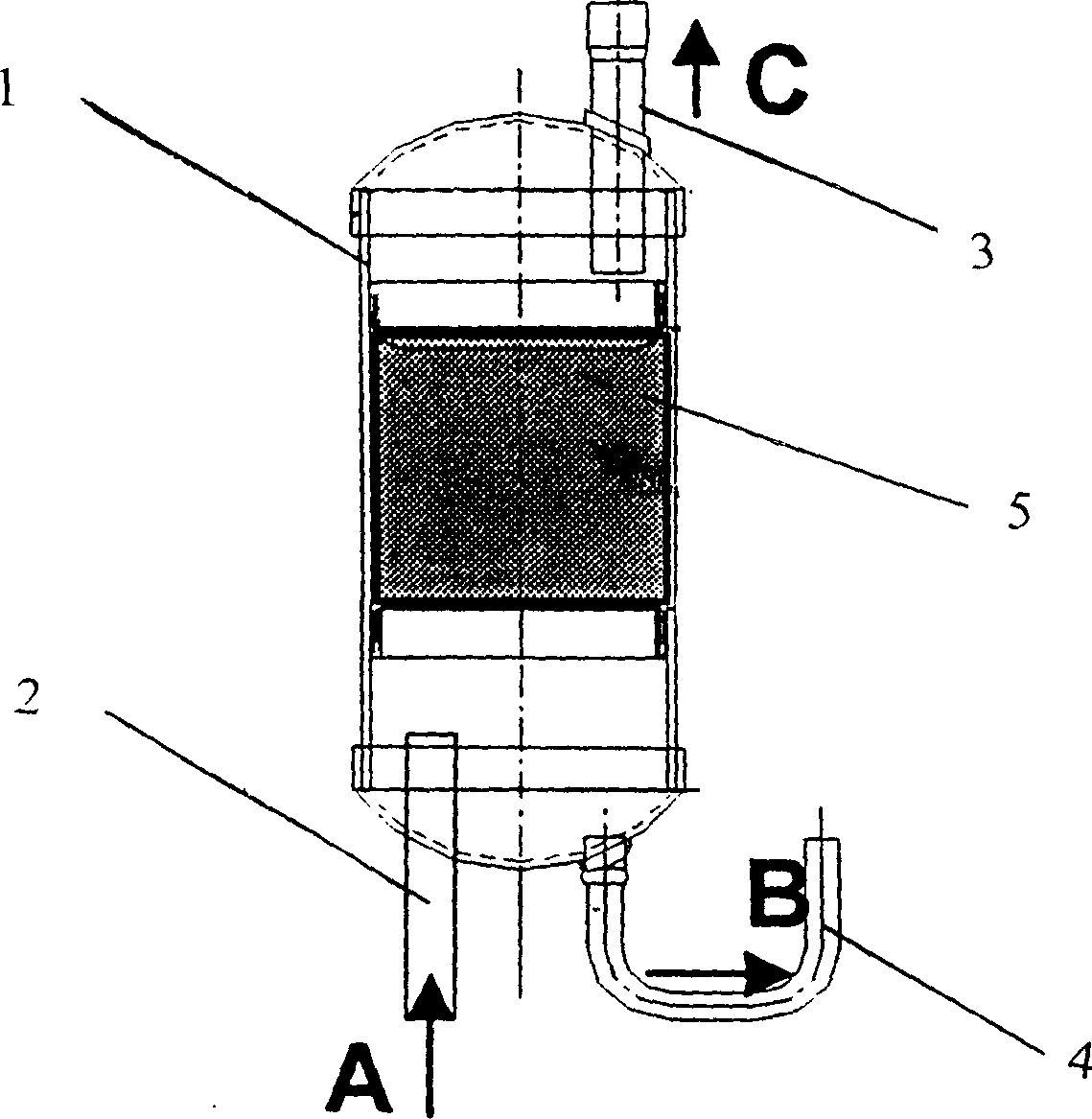
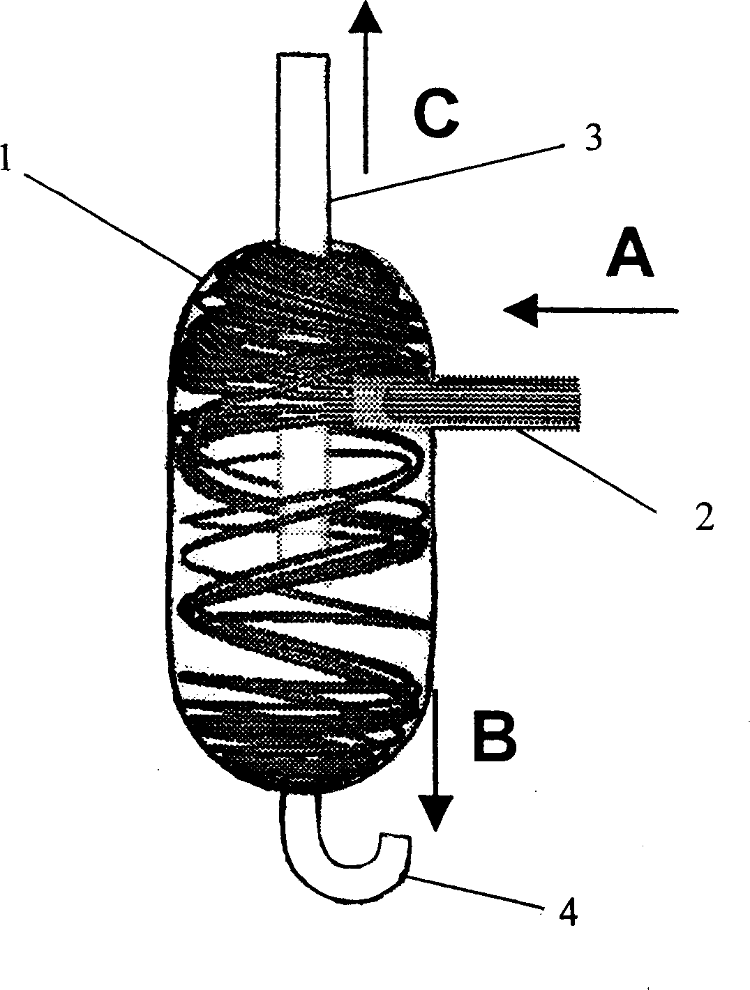
[0016] The specific embodiment of the present invention will now be described in conjunction with the accompanying drawings. Such as figure 2 As shown, the novel oil separator involved in the present invention includes a tank body 1 with a cylindrical structure, and the wall thickness of the tank body is 1.2 mm. The side of the tank body is inserted into the intake pipe 2, the top is inserted into the exhaust pipe 3, and the bottom is provided with an oil return pipe 4. The intake pipe 2 , the exhaust pipe 3 and the oil return pipe 4 communicate with the inside of the tank body 1 . The bottom end of the exhaust pipe 3 inserted from the top is inserted into the inner center of the tank body 1 . There is an angle of 120° between the inlet pipe 2 inserted from the side of the tank body 1 and the axis of the tank body, and the end of the inlet pipe 2 inserted into the tank body is higher than the bottom end of the exhaust pipe 3 .


PUM


Abstract

The invention discloses a new type oil separator, which comprises the following parts: cylindrical tank with 1.2 mm thickness, inlet pipe on the lateral face of tank, drainage pipe on the top of tank and oil return pipe on the bottom, wherein the separation angle of inlet pipe and tank axial central line displays 120 deg; one end of inlet pipe plugged in the tank is higher than the bottom of drainage pipe; when the coolant (R22) with lubrication oil enters into the oil separator tank, the oil gathers on the bottom of separator tank by the centrifugal effort, which flows into the compressor through oil return pipe. The invention overcomes the present waste of pressure drag and saves the filter net, which improves the compressor frequency and reduces the manufacturing cost.

Description

technical field [0001] The invention relates to an oil separator for a compressor, in particular to an oil separator which realizes oil separation by utilizing high-pressure mixed gas entering a tank body of the separator to rotate at a high speed. Background technique [0002] Generally speaking, the oil separator of the compressor is set between the exhaust port of the compressor and the condenser, which is used to separate the lubricating oil in the high-pressure gas discharged from the compressor, so that excess oil does not enter the condenser and evaporator, In order to prevent the compressor from lacking oil, otherwise it will cause great damage to the compressor. [0003] figure 1 It is an existing oil separator of a compressor, which uses filler placed in the tank to achieve the effect of separating refrigerant (R22) and lubricating oil. The refrigerant gas containing lubricating oil discharged from the compressor enters the oil separator from the intake pipe at t...

Claims


Application Information

Patent Timeline
Patent Type & Authority Applications(China)
IPC IPC(8): F25B43/02
Inventor 刘鸿卿
Owner LG ELECTRONICS (TIANJIN) APPLIANCES CO LTD
Why Eureka
Try Eureka