Image read device and vibration prevention device using same

An image reading device and image technology, applied in image communication, optics, instruments, etc., can solve the problems of high price of flywheel 17, increase of installation area, enlargement of the device, etc., achieve simple structure, prevent vibration, and reduce installation area Effect

Inactive Publication Date: 2006-11-01
NEC CORP
View PDF1 Cites 3 Cited by
  • Summary
  • Abstract
  • Description
  • Claims
  • Application Information

AI Technical Summary

Problems solved by technology

[0015] However, in Figure 5 In the existing image reading device shown in , the flywheel 17 installed on the motor 15 is expensive, and there is a disadvantage of cost i

Method used


Image

  • Image read device and vibration prevention device using same
  • Image read device and vibration prevention device using same
  • Image read device and vibration prevention device using same

Examples


Example Embodiment

[0037] (Embodiment 1)

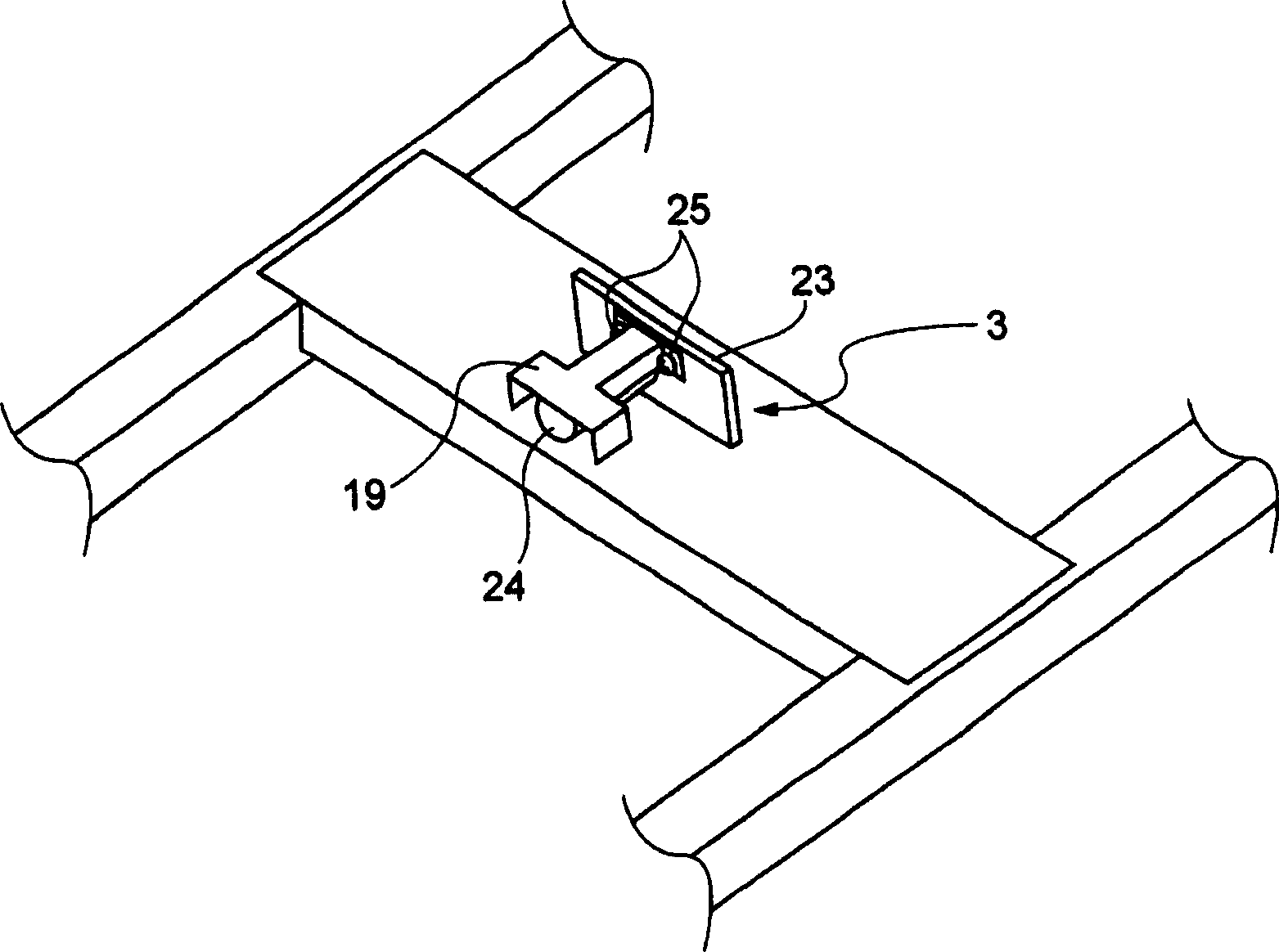
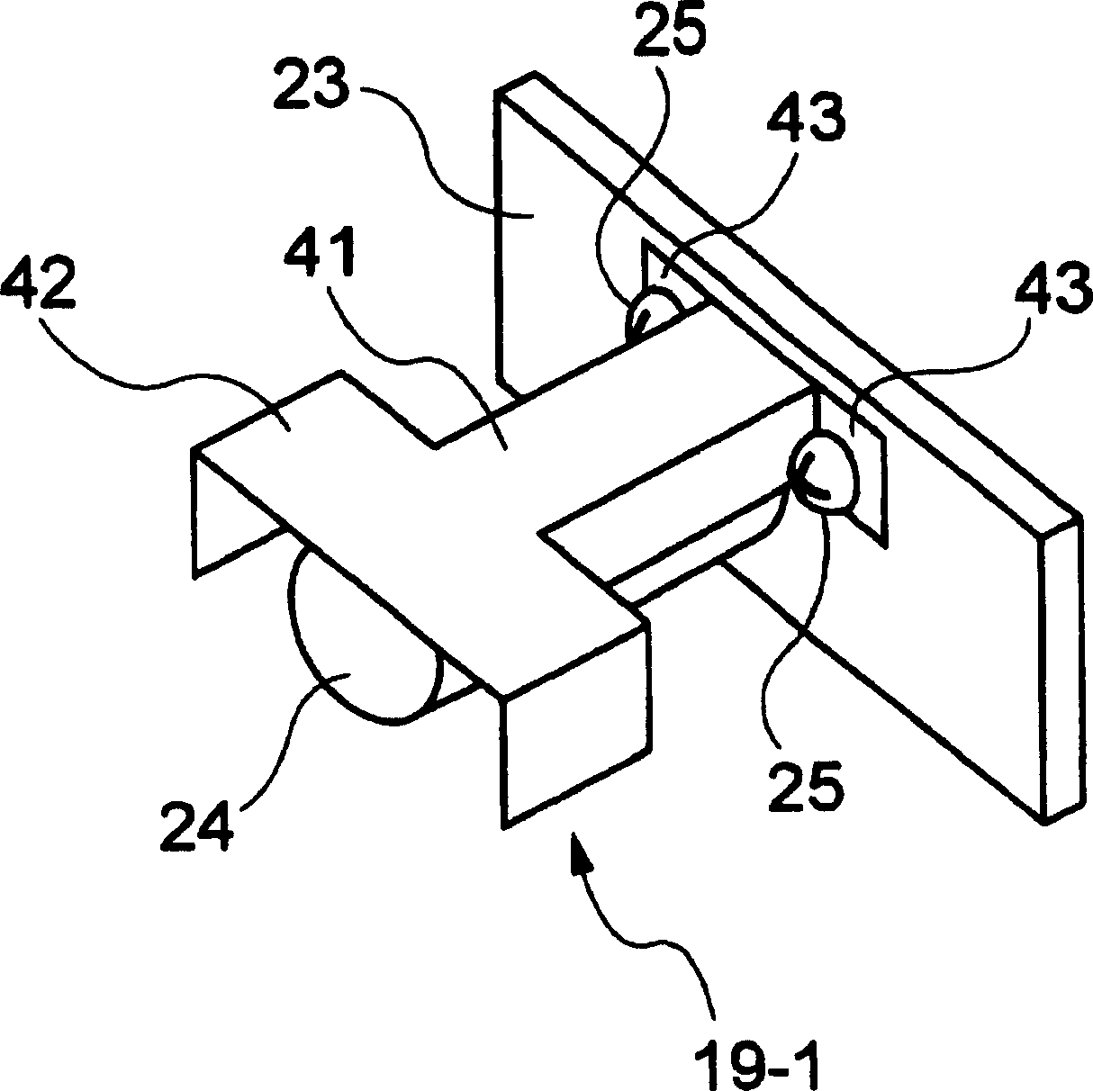
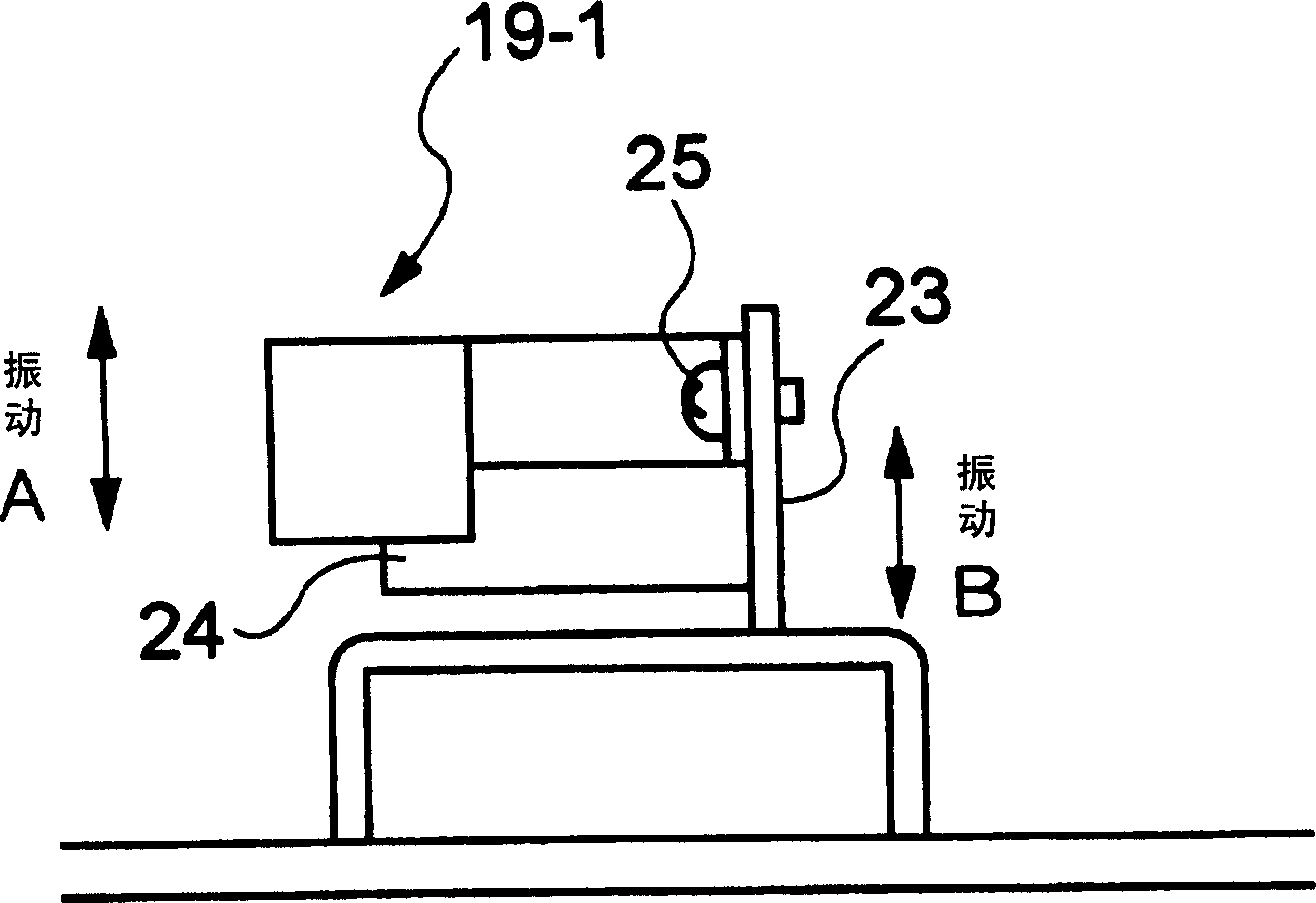
[0038] figure 2 It is a perspective view of the first embodiment of the anti-vibration device of the present invention. In addition, for this figure with figure 1 The same structural parts are given the same symbols, and therefore descriptions thereof are omitted. With reference to this figure, the weight 19-1 is composed of the following components: a first component 41, whose cross section is U-shaped; The first member 41 is wide; the third member 43 is provided at the other end of the first member 41 , and the first member 41 to the third member 43 are integrally formed.

[0039] However, it is also possible to use the first member 41 and the second member 42 as independent members, and adopt a mutually joined structure.

[0040] In addition, a hole (not shown) through which the screw 25 passes is formed in the third member 43 , and the weight 19 - 1 is attached to the CCD substrate 23 by the screw 25 through the hole. In addition, the installat...

Example Embodiment

[0044] (Example 2)

[0045] Figure 4 It is a perspective view of the second embodiment of the anti-vibration device of the present invention. In addition, for this figure with figure 2 The same structural parts are given the same symbols, and therefore descriptions thereof are omitted. Referring to the figure, the weight 19-2 is different in shape from the weight 19-1 in the first embodiment in that the fourth member 44 corresponding to the second member 42 in the first embodiment is formed as a flat plate. Other shapes are the same as the first embodiment.

[0046] According to the second embodiment of the present invention, since the fourth member 44 does not need to be bent, the number of steps can be reduced.

[0047] (industrial availability)

[0048] In this embodiment, as the shape of the weight 19, figure 2 and Figure 4 An example is shown in , but it is not limited to these. As long as the following conditions are satisfied, the present invention can also b...


PUM


Abstract

The present invention provides an image reading device that does not require a flywheel attached to a motor and a weight attached to a transmission shaft, and can prevent vibration of an optical member. By means of screws (25), a weight (19) in the shape of a cantilever beam with a front-end load corresponding to the number of vibrations of the vibration amplitude from a vibration source such as a motor (15) and attenuating the vibration amplitude (19) is attached to the image reading device. On the CCD substrate (23) of the optical member (3) inside. The weight (19) is made of the following members: the first member (41) has a U-shaped cross section; the second member (42) is located at the end of one end of the first member (41), and the cross-section is U-shaped and The width is wider than that of the first member (41); the third member (43) is arranged at the end of the other end of the first member (41), and the first member (41) to the third member (43) are integrally formed.

Description

technical field [0001] The present invention relates to an image reading device and an anti-vibration device used therefor, and more particularly, to an image reading device such as a copier, a facsimile machine, an allied machine, and a scanner, and an anti-vibration device therefor. Background technique [0002] Figure 5 It is a plan view showing an example of the structure of a conventional image reading device, Image 6 Yes Figure 5 A-A` section view in . [0003] refer to Figure 5 and Image 6 , an example of an existing image reading device, its structure includes: drum 1; transmission shaft 2; optical unit 3; light unit 4; reflector unit 5; wire 6; 11; pulley 12 (12-1, 12-2); reflector 13 (13-1~13-3); synchronous belt 14; motor 15; belt wheel 16; flywheel 17; heavy hammer 18; An imaging device substrate (as an example, a CCD (Charge Coupled Device) substrate, hereinafter referred to as a CCD substrate) 23 ; and a lens 24 . [0004] Optical unit 3 is made up of ...

Claims


Application Information

Patent Timeline
IPC IPC(8): G02B26/10H04N1/04
Inventor 玉村克喜安藤英幸
Owner NEC CORP
Why Eureka
Try Eureka