Eureka AIR delivers breakthrough ideas for toughest innovation challenges, trusted by R&D personnel around the world.

Vehicle behavior estimating device and vehicle behavior controlling device

Inactive Publication Date: 2005-05-12
DENSO CORP
View PDF8 Cites 4 Cited by
  • Summary
  • Abstract
  • Description
  • Claims
  • Application Information

AI Technical Summary

Benefits of technology

[0009] It is an object of the present invention to provide a technology that properly suppresses vibrations of individual parts of a vehicle by a simple process by uniformly treating causes generating the vibrations of the individual parts of the vehicle.

Problems solved by technology

The difference between the driving torque and road-surface transmitting torque is energy that is undesirably consumed in the vibration or the like of the individual vehicle parts such as the vehicle body and the shafts (including driving wheels).

Method used


Image

  • Vehicle behavior estimating device and vehicle behavior controlling device
  • Vehicle behavior estimating device and vehicle behavior controlling device
  • Vehicle behavior estimating device and vehicle behavior controlling device

Examples


Embodiment Construction

[0045] Hereinafter, an example which the present invention is directed to will be explained by using drawings. Here, an embodiment of the present invention is not limited to the example below, and can be modified into various embodiments as long as it falls within a technical region of the present invention.

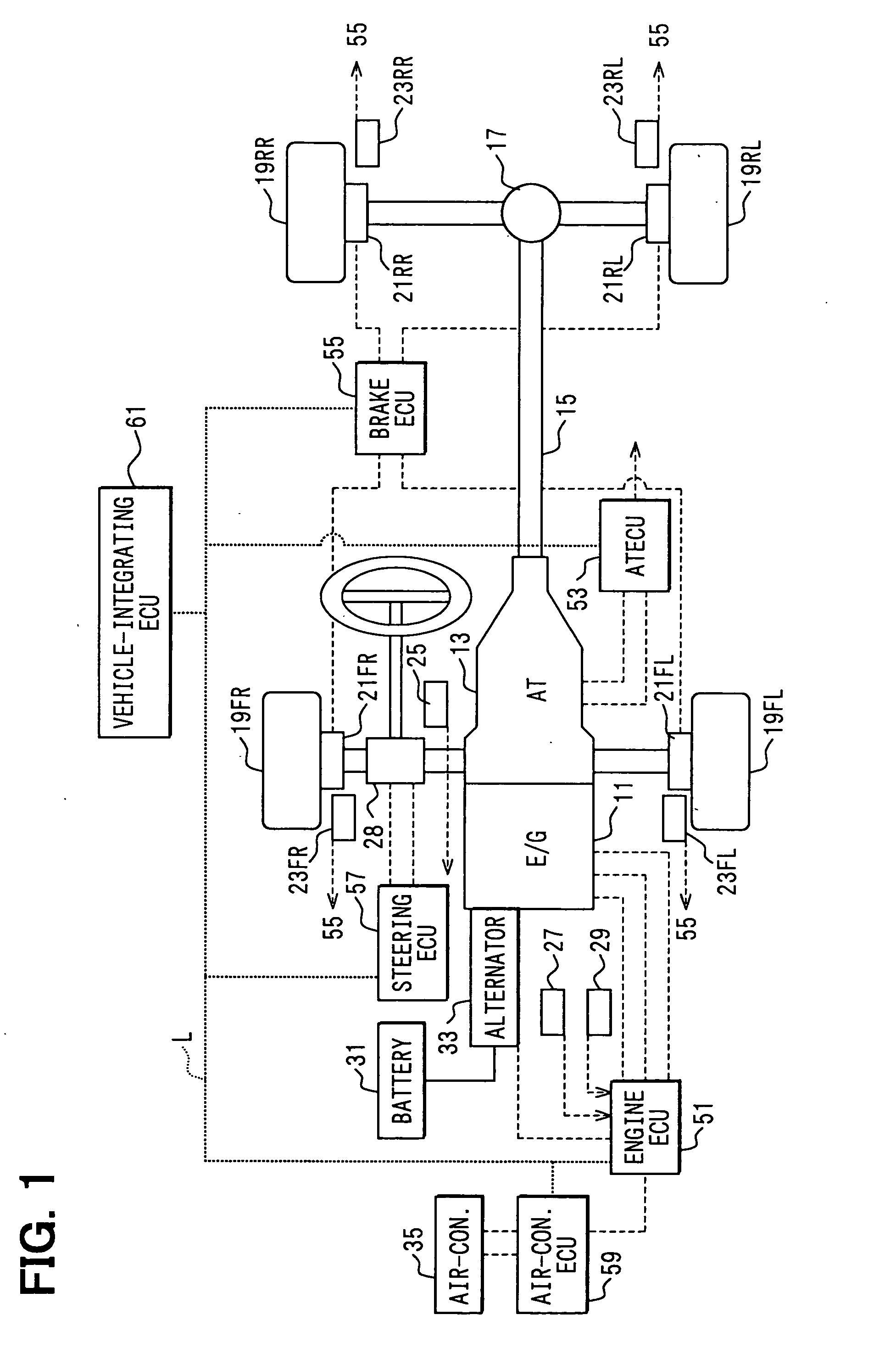
[0046]FIG. 1 shows a block diagram showing a structure of a vehicle behavior controlling device of an example. In the example, a vehicle behavior estimating device and vehicle behavior controlling device of the present invention are adopted to a front-engine and rear-driving (FR) type vehicle.

[0047] As shown in FIG. 1, in this vehicle, an engine 11 (or internal combustion engine) as driving force providing means outputs an output torque as a driving torque to a driving shaft 15 via an automatic transmission 13 (multiple-step transmission, hereinafter referred to as AT) as a transmission. The driving torque outputted to the driving shaft 15 is divided into a left-rear wheel 19RL...


PUM


Abstract

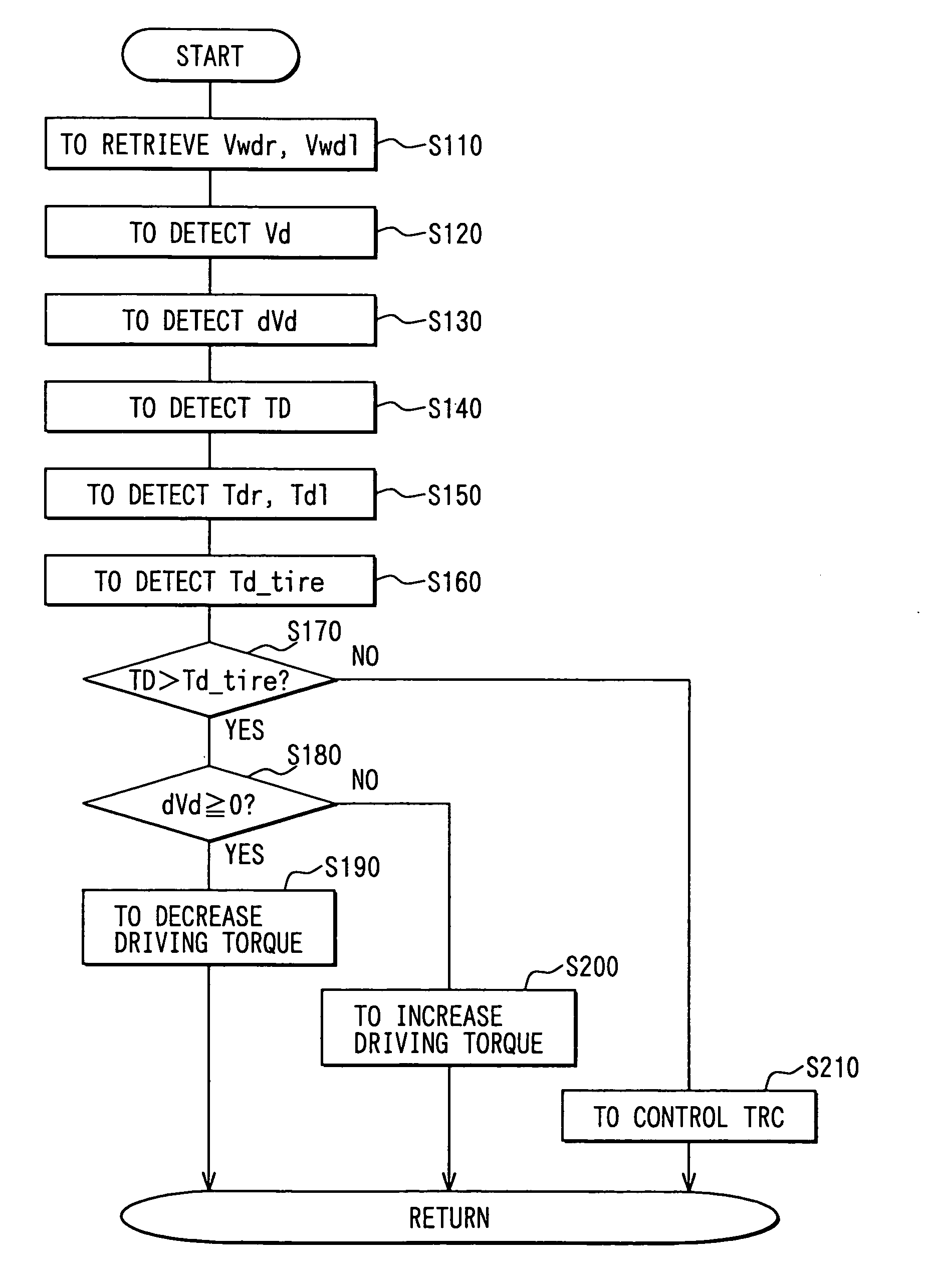
While a driving torque TD outputted to a driving shaft via an AT from an engine is detected, a road-surface transmitting torque Td_tire is detected based on rotation speeds Vwdr, Vwdl of vehicle driving wheels, a vehicle body speed Vd, and driving torques Tdr, Tdl, all of which are previously detected. The driving torque TD and the road-surface transmitting torque Td_tire are then compared to each other. When TD>Td_tire, the driving torque from an engine is controlled so as to decrease a value of (TD−Td_tire). The vibrations of individual vehicle parts are thereby decreased.

Description

CROSS REFERENCE TO RELATED APPLICATIONS [0001] This application is based on and incorporates herein by reference Japanese Patent Application No. 2003-380336 filed on Nov. 10, 2003. FIELD OF THE INVENTION [0002] The present invention relates to a vehicle behavior estimating device that is capable of estimating a vibration state of a vehicle at traveling, and a vehicle behavior controlling device that suppresses the vibration state with the vehicle behavior estimating device. BACKGROUND OF THE INVENTION [0003] Conventionally, for instance, as described in Patent document 1, it is known that there is a device that suppresses resonance by controlling a torque outputted to a shaft of a vehicle driving system when the vehicle driving system resonates. [0004] The device previously possesses map data formed by specifying by experiments in which region of a vehicle speed, a torque command value, or the like a resonance takes place. The device then estimates whether the resonance takes place ...

Claims


Application Information

Patent Timeline
IPC IPC(8): B60K28/16F02D45/00B60T8/175F02D29/00F02D29/02F02D41/04
CPCB60K28/16B60T8/175B60W2520/10B60W2710/0666B60W2520/30B60W2550/148B60W2520/105B60W2552/40
Inventor SAWADA, MAMORUMATSUMOTO, TOSHIKITASHIRO, TSUTOMUMABUCHI, MAMORUFUJII, TAKEHITO
Owner DENSO CORP
Why Eureka
Eureka Blog
Learn More