

Foot massaging apparatus
A technology for toes and feet, applied in the field of foot massage machines, can solve the problems of inability to rub the toes, mechanical rotation stimulation, and users being easily bored and so on.
- Summary
- Abstract
- Description
- Claims
- Application Information
AI Technical Summary
Problems solved by technology
Method used
Image

Examples
no. 1 example
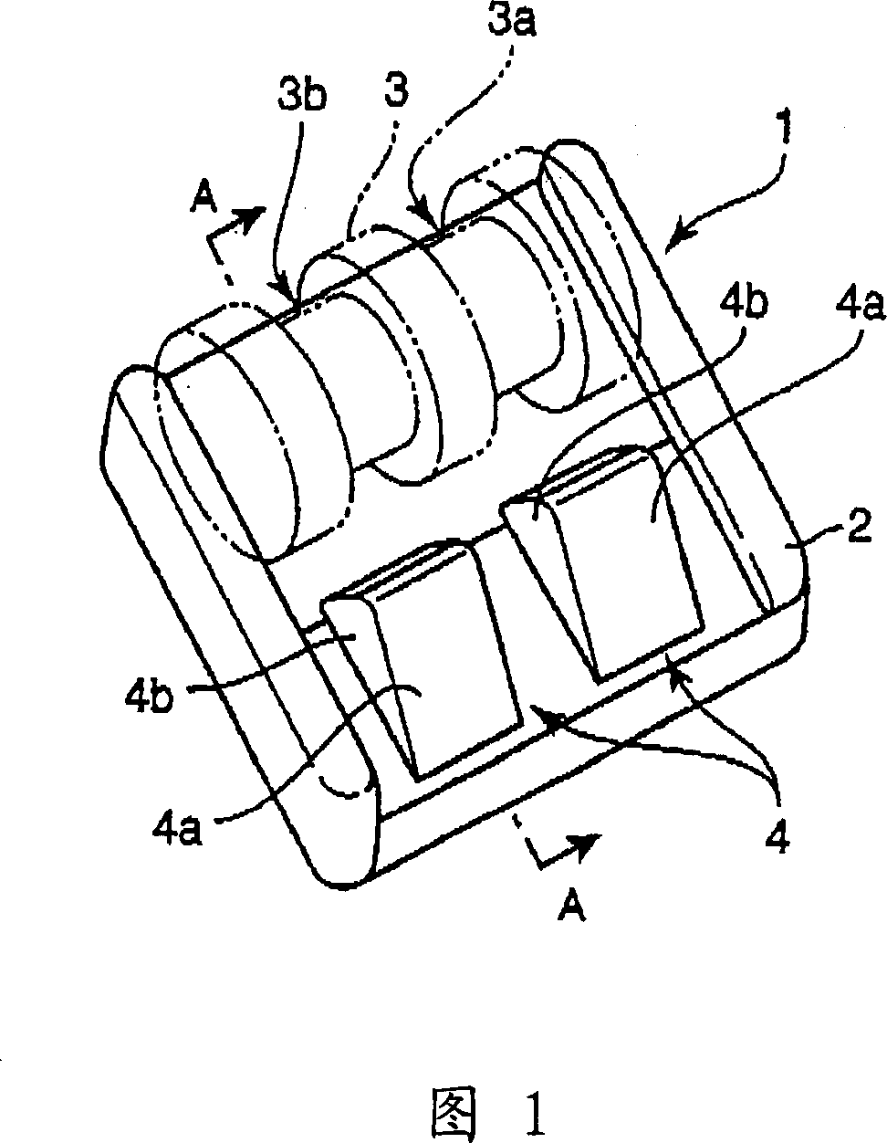
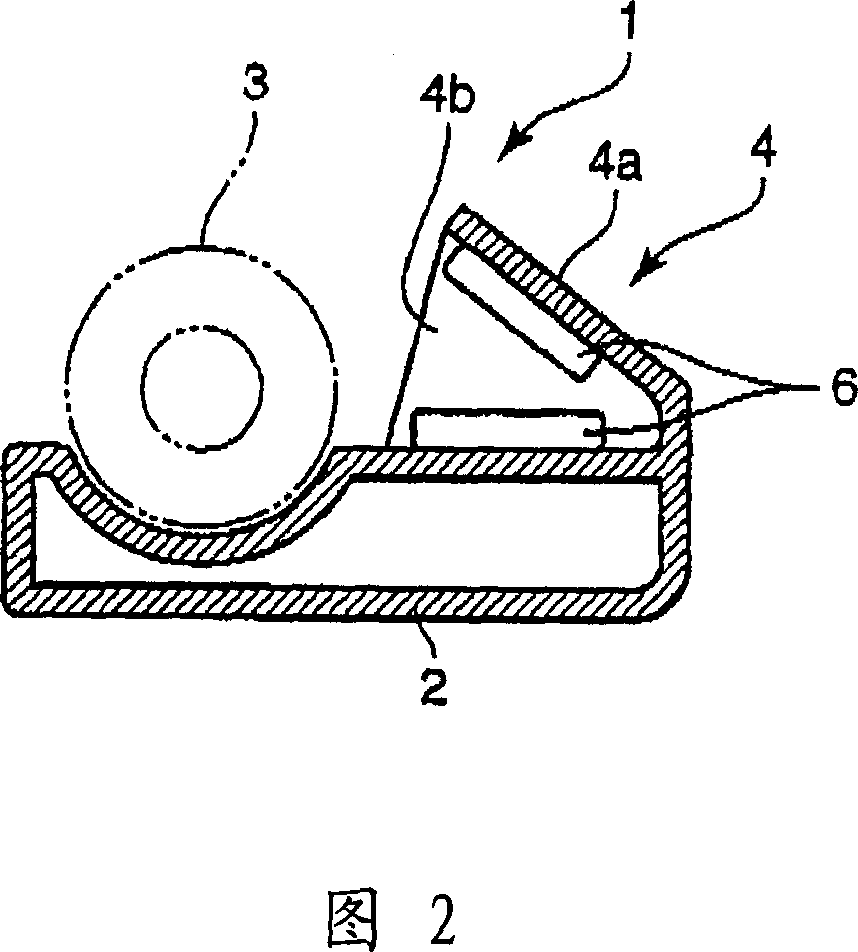
[0047] Fig. 1 is a perspective view showing the appearance of a foot massager according to a first embodiment of the present invention, and Fig. 2 is a sectional view taken along line A-A of Fig. 1 .
[0048] In this foot massage machine 1 , a roller rotation unit 3 and a toe kneading unit 4 are provided on a foot resting main body 2 . The roller rotating part 3 is provided at the rear side of the main body part 2 , and the toe kneading part 4 is provided at the front position of the roller rotating part 3 .
[0049] The roller rotating part 3 may have a structure capable of repeatedly pressing the foot, the structure of Patent Document 1 or 2, or other structures. The left foot is placed on the left side part 3 a of the roller rotating part 3 , and the right foot is placed on the right side part 3 b of the roller rotating part 3 .
[0050] The toe kneading part 4 is integrated with the main body part 2 in this embodiment, and is arranged on the front side of the left side pa...
Embodiment 2
[0054] Fig. 4 is a plan view showing a foot massager according to a second embodiment of the present invention, and Fig. 5 is a perspective view of a toe kneading part of the foot massager as seen obliquely from the front. In addition, the same symbols are used for the same parts as those of the first embodiment.
[0055]In this foot massage machine 11, the roller rotating part 3 and the toe kneading part 14 are provided on the main body part 12 for placing feet in the same positional relationship as before, and the configuration of the roller rotating part 3 is the same as before.
[0056] The toe kneading part 14 is formed separately from the main body part 12 in this embodiment, and is provided as a pair on the left and right. Next, the toe kneading part 14 and its moving mechanism will be described.
[0057] Each toe kneading part 14 has an opening for toe insertion on the rear side, and air cells 6 contracted and inflated by exhausting and supplying air are provided on t...
no. 3 example
[0062] Fig. 6 is a plan view showing a foot massager according to a third embodiment of the present invention, and Fig. 7 is a perspective view of a toe kneading part of the foot massager as seen obliquely from the front.
[0063] In this foot massage machine 21, the roller rotation part 3 and the toe kneading part 24 are provided in the foot rest main body part 22 in the same positional relationship as before, and the configuration of the roller rotation part 3 is the same as before.
[0064] The toe kneading part 24 is formed separately from the main body part 22 in this embodiment, and is provided as a pair on the left and right. Next, the toe kneading unit 24 and the moving mechanism will be described.
[0065] Each toe kneading part 24 has an opening for toe insertion on the rear side, and air cells 6 that contract and expand by discharging and supplying air are provided on the upper and lower surfaces inside.
[0066] The moving mechanism has: a pair of supporting holes...
PUM
 Abstract
Description
Claims
Application Information