Crosshead bearing for large two-stroke diesel engine

A cross-head, two-stroke technology, used in engine lubrication, rotating bearings, cross-heads, etc., can solve problems such as high peak pressure, steep pressure gradient, etc., and achieve the effect of low dynamic load

Active Publication Date: 2007-04-04
曼能解决方案(曼能解决方案德国股份公司)分公司
View PDF1 Cites 5 Cited by
  • Summary
  • Abstract
  • Description
  • Claims
  • Application Information

AI Technical Summary

Problems solved by technology

[0005] The disadvantage of large oil feed holes and transverse slits in the middle of the most heavily loaded part of the bearing is that the oil film is interrupted, i.e. axially separated, which leads to higher peak pressures and steeper pressure gradients

Method used


Image

  • Crosshead bearing for large two-stroke diesel engine
  • Crosshead bearing for large two-stroke diesel engine
  • Crosshead bearing for large two-stroke diesel engine

Examples


Embodiment Construction

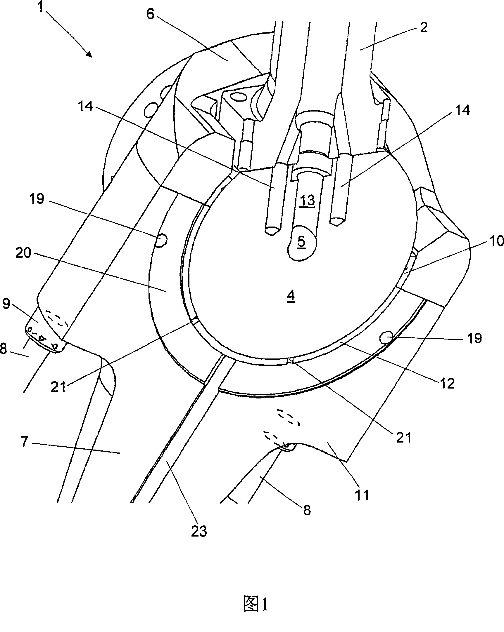
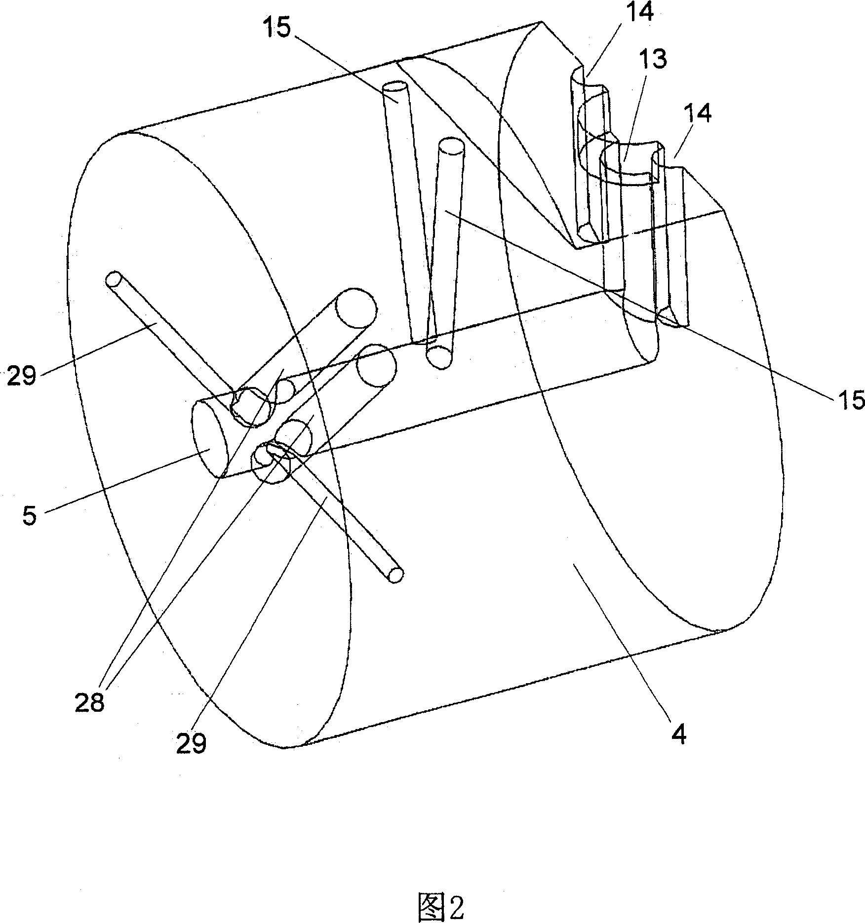
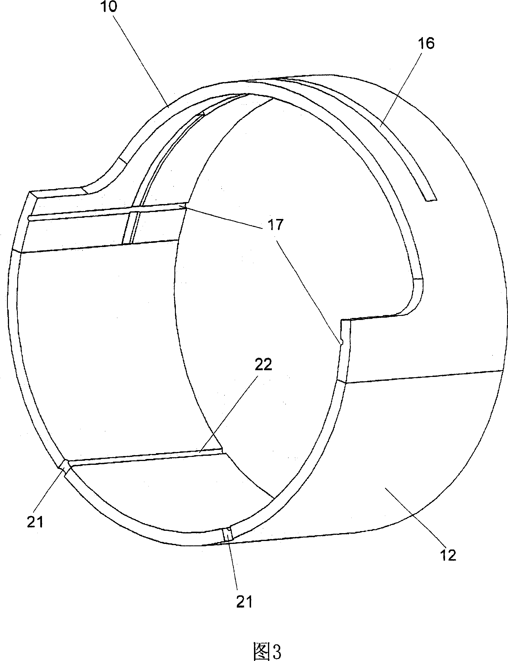
[0032] A crosshead bearing 1 for a large two-stroke diesel engine according to a first embodiment is shown in FIG. 1 . The piston rod 2 is connected with a hydraulic fastening bolt to a crosshead bearing 4 provided with an axial bore 5 closed at its axial end. A one piece crosshead bearing cap 6 with an angular cutout for the piston rod 2 is fixed to the connecting rod 7 by bolts 8 and nuts 9 tightened by hydraulic jacks. The bearing cap 6 is provided with a thin walled upper steel casing 10 adjoining the inner bearing surface with white metal. The connecting rod 7 is provided with an integral seat 11 holding a thin-walled lower steel shell 12 adjoining the inner bearing surface, for example with white metal. The lower shell 12 within the seat 11 effectively functions as a unitary member, but may also be formed from two or more sections that are stacked closely together to form a continuous bearing surface, i.e. between the parts forming the shell. The transitions are tight ...


PUM


Abstract

A positively dimensioned crosshead bearing (1) having a crosshead journal (4) with an axial bore (5) receiving system oil via a flexible connection. The system oil is distributed to the piston, the bearing surface of the crosshead and the crankpin bearing. At least two axial lubrication grooves (22) are disposed in the lower bearing surface. The bearing surface between the at least two axial lubrication grooves (22) is not interrupted nor distorted.

Description

technical field [0001] This invention relates to crosshead bearings for large two-stroke diesel engines, and more particularly to arrangements for providing lubricating oil to the bearing surfaces of the crosshead. Background technique [0002] The crosshead is an important heavy duty engine component which must be very reliable in operation. Thus, conventional crossheads are relatively heavy moving pieces, increasing the dynamic load on other engine components. [0003] EP 0 199 906 discloses a crosshead bearing for a large two-stroke diesel engine designed to be lubricated by lubricating oil supplied under pressure through a lubrication line connected to the upper part of the connecting rod. The channel in the upper part of the connecting rod leads to an oil feed hole in the bearing shell, and the oil feed hole leads to a lubricating oil pocket formed in the bearing surface of the shell. Lubricant packs need to be supplied with lubricating oil at a relatively high pressu...

Claims


Application Information

Patent Timeline
Patent Type & Authority Applications(China)
IPC IPC(8): F16C33/10F16C5/00
CPCF16C5/00F01M2001/066F16C17/026F16C33/1065
Inventor 延斯·拉特曼尼尔斯·亨里克·内伊高
Owner 曼能解决方案(曼能解决方案德国股份公司)分公司
Why Eureka
Try Eureka