Driving method for liquid crystal display

A technology of a liquid crystal display device and a driving method, which is applied to static indicators, instruments, etc., can solve problems such as uneven display of a liquid crystal display device, and achieve uniform display effects and uniform display

Inactive Publication Date: 2007-04-18
INNOCOM TECH SHENZHEN +1
View PDF0 Cites 13 Cited by
  • Summary
  • Abstract
  • Description
  • Claims
  • Application Information

AI Technical Summary

Problems solved by technology

[0008] In order to solve the problem of non-uniform display of the picture of the liquid crystal display device, it is necessary to provide a driving method for uniform display of the picture of the liquid crystal display device

Method used


Image

  • Driving method for liquid crystal display
  • Driving method for liquid crystal display
  • Driving method for liquid crystal display

Examples


Embodiment Construction

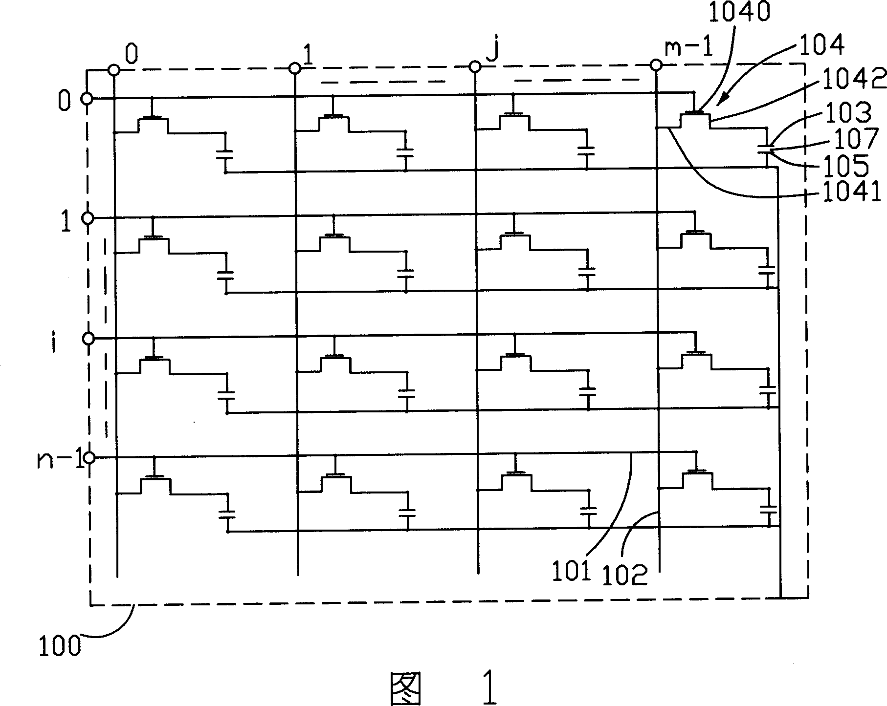
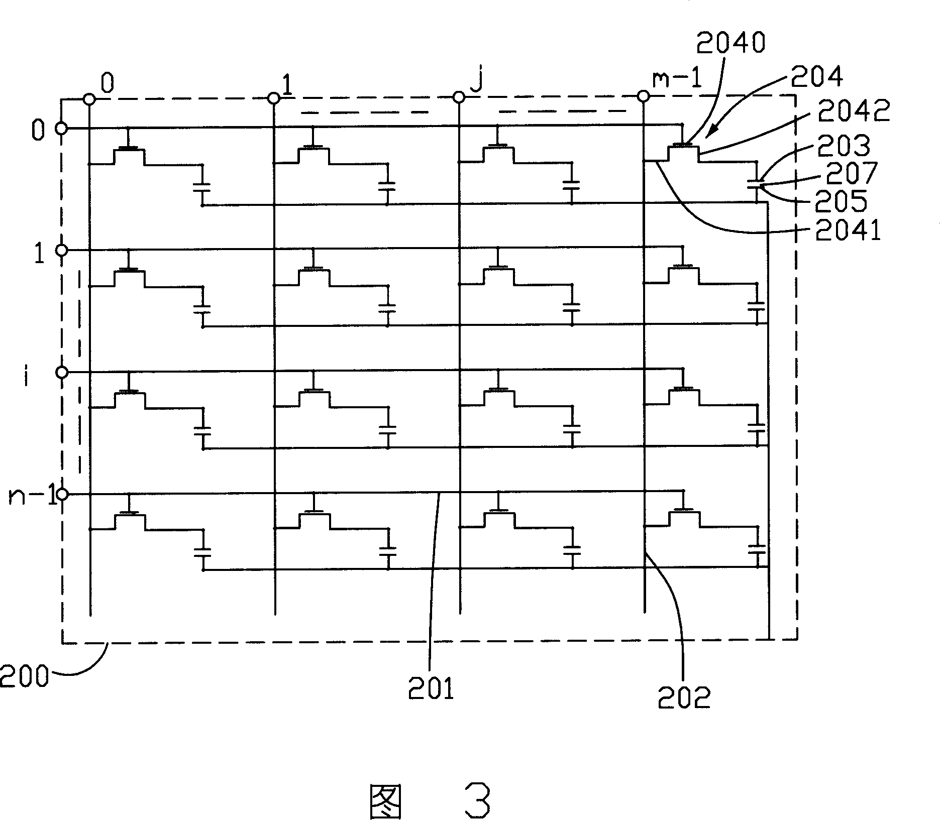
[0021] Please refer to FIG. 3 , which shows a liquid crystal display device 200 driven by the driving method of the present invention. The liquid crystal display device 200 includes n rows of scan electrodes 201 parallel to each other, m columns of data electrodes 202 parallel to each other and vertically insulated and intersected with the n rows of scan electrodes 201, a plurality of common electrodes 205, and a plurality of them are used as switching elements to drive the pixel electrodes 203 TFT 204 and a backlight module (not shown) for providing planar light. The thin film transistors 204 are located at the intersections of the scan electrodes 201 and the data electrodes 202 , their gates 2040 are connected to the scan electrodes 201 , their sources 2041 are connected to the data electrodes 202 , and their drains 2042 are connected to the pixel electrodes 203 . Each scanning row includes m pixel electrodes 203 , and each pixel electrode 203 and each common electrode 205 f...


PUM


Abstract

The invention relates to a driving method to drive display device to display image data. The device includes backlight module and plural liquid crystal pixels. And the backlight module contains plural light emitting brightness levels. The driving method includes following steps: separating the image display section to plural sub-display sections, when liquid crystal open or close at the display section, the backlight would open or close at the sub-display section, controlling the switch state of the liquid crystal pixel and light emitting brightness level of backlight module and light emitting time to realize gray scale display. The invention could make the image of LCD device equal.

Description

【Technical field】 [0001] The invention relates to a driving method of a liquid crystal display device. 【Background technique】 [0002] Due to the advantages of light weight, thin thickness, and low power consumption, liquid crystal display devices are widely used in modern information equipment such as televisions, notebook computers, mobile phones, and personal digital assistants. [0003] A prior art liquid crystal display device can refer to FIG. 1, the liquid crystal display device 100 includes n rows of scan electrodes 101 parallel to each other, m columns of data electrodes 102 parallel to each other and vertically insulated from the n rows of scan electrodes 101, and multiple A thin film transistor (Thin Film Transistor, TFT) 104 is used as a switching element to drive the pixel electrode 103 . The plurality of thin film transistors 104 are located at the intersection of the scan electrode 101 and the data electrode 102, the gate 1040 of the thin film transistor 104 ...

Claims


Application Information

Patent Timeline
Patent Type & Authority Applications(China)
IPC IPC(8): G09G3/36G09G3/20G02F1/133
Inventor 陈景丰陈龙宽陈思孝张智胜廖文杰陈鹊如谢朝桦
Owner INNOCOM TECH SHENZHEN
Why Eureka
Try Eureka