Power supply and circuit board output structure thereof

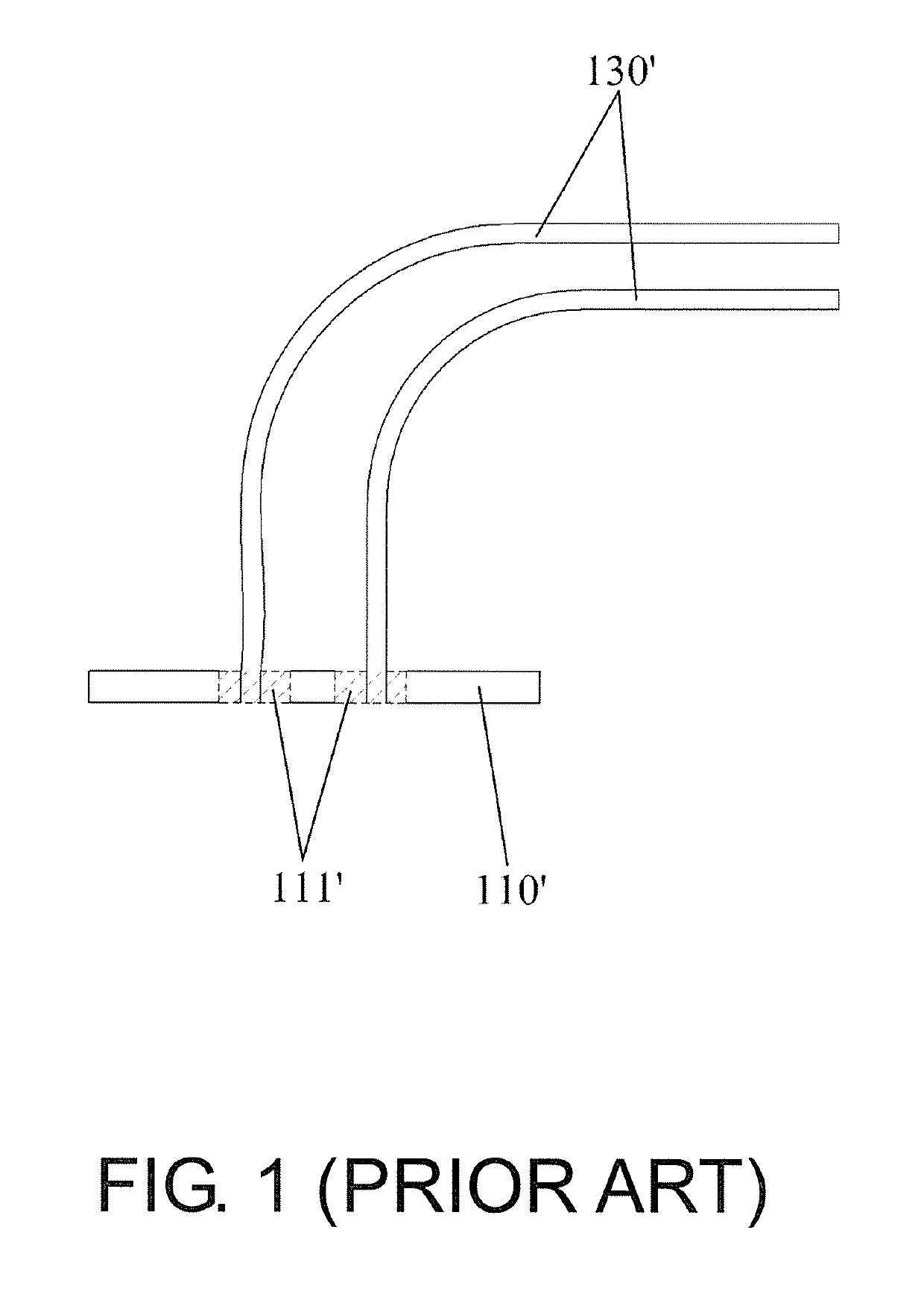
a power supply and circuit board technology, applied in the direction of printed circuits, non-printed electric components of printed circuits, association, etc., can solve the problems of complex replacement, output wire b>130/b>, connected to the output terminal, etc., to prevent the damage of output wires, simple and convenient replacement, the effect of reducing the angle and stress of the output wires inserted on the first connection pi

Active Publication Date: 2019-05-21
3Y POWER TECH TAIWAN
View PDF2 Cites 0 Cited by
  • Summary
  • Abstract
  • Description
  • Claims
  • Application Information

AI Technical Summary

Benefits of technology

[0006]The invention aims to provide a circuit board output structure capable of reducing R angle and stress of the wires and avoiding assembly problems without replacing the whole circuit board.
[0007]Another goal of the invention is to provide a power supply, which can reduce R angle and stress of the wires and avoid assembly problems without replacing the whole circuit board when the output specification needs to be changed.
[0019]Compared with the prior art, in the circuit board output structure of the invention, each metal connection stand includes the first connection piece showing the included angle with respect to the circuit board, and the connection holes for electrically connecting the output wires are formed on the first connection piece. Accordingly, when it is required to change the output specification of the power supply, the replacement can be more simple and convenient since the metal connection stand may be directly replaced, and quantity and aperture of the connection holes on the first connection piece may be adjusted without replacing the whole circuit board. In addition, because the first connection piece has the included angle specified with respect to the circuit board, R angle and stress of the output wires inserted on the first connection piece may be reduced, so as to prevent the output wires from damage, or prevent the output wires from detaching from the circuit board or having poor electrical contact after the assembly. Compared with the prior art, larger area can be provided for inserting more of the output wires while still occupying the same area of the circuit board. The first connecting piece is separated from the circuit board by a distance so effective dissipation can be provided when large current is to be transmitted. Correspondingly, the power supply having said circuit board output structure can also provide the same technical effects of the above.

Problems solved by technology

Also, other electronic components on the circuit board 110′ need to be removed for re-soldering, and thus the replacement can be complicated.
However, due to limitations by the space inside the power supply and design of an output terminal thereof, the wires 130′ can only be connected to the output terminal of the power supply after being bent at an angle.
Consequently, R angle and stress of the wires 130′ are increased, making the output wire 130′ prone to damage, or detaching from the circuit board 110′ or having poor electrical contact.

Method used


Image

  • Power supply and circuit board output structure thereof
  • Power supply and circuit board output structure thereof
  • Power supply and circuit board output structure thereof

Examples


Embodiment Construction

[0025]Reference will now be made in detail to the present preferred embodiments of the invention, examples of which are illustrated in the accompanying drawings. Wherever possible, the same reference numbers are used in the drawings and the description to refer to the same or like parts.

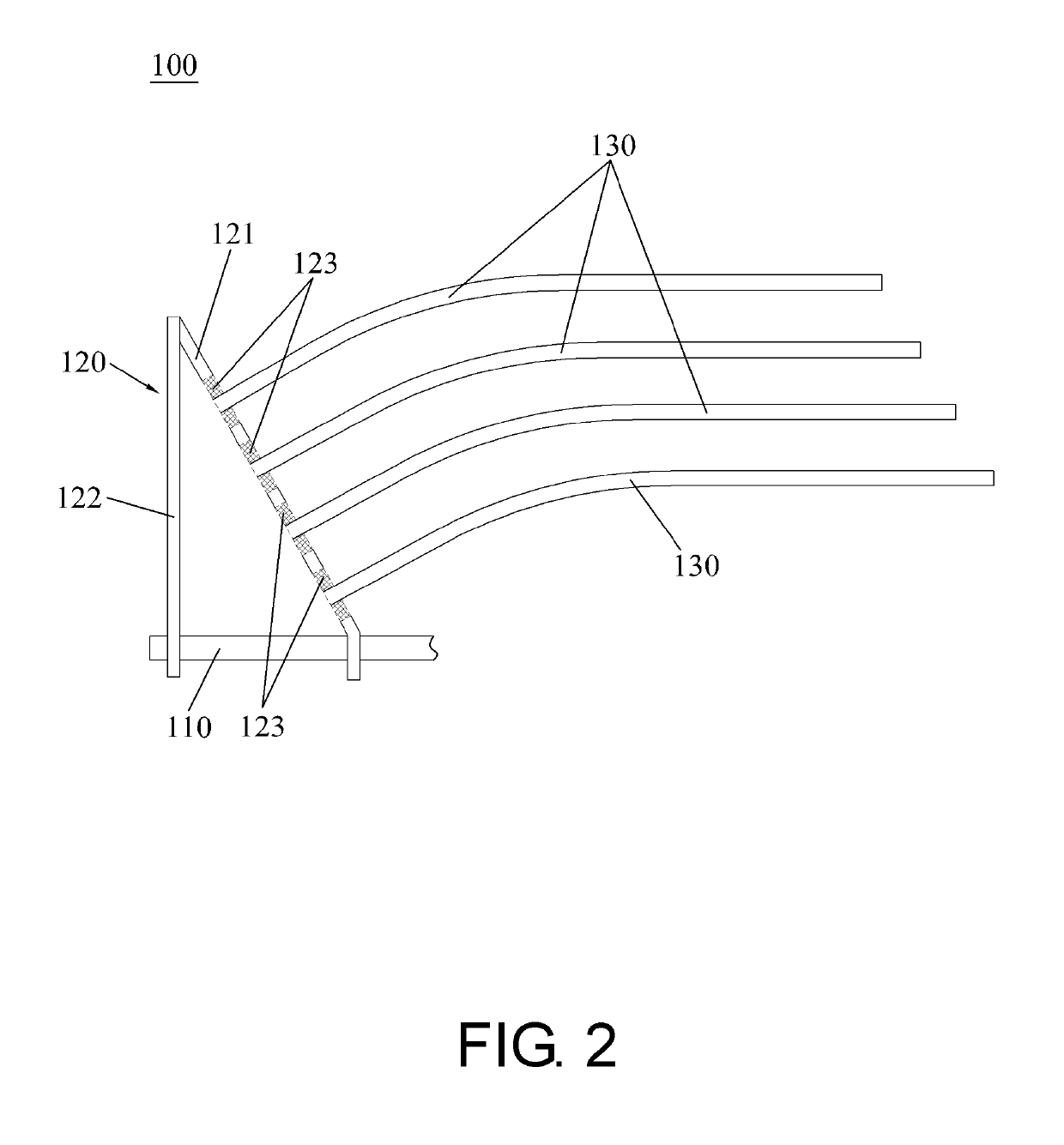
[0026]As shown by FIG. 2, a circuit board output structure 100 provided by the invention includes a power output section 110 disposed on a circuit board and at least one metal connection stand 120 electrically connected to the power output section 110. Each of the metal connection stand 120 may be provided to connect at least one output wire 130 of a corresponding specification.

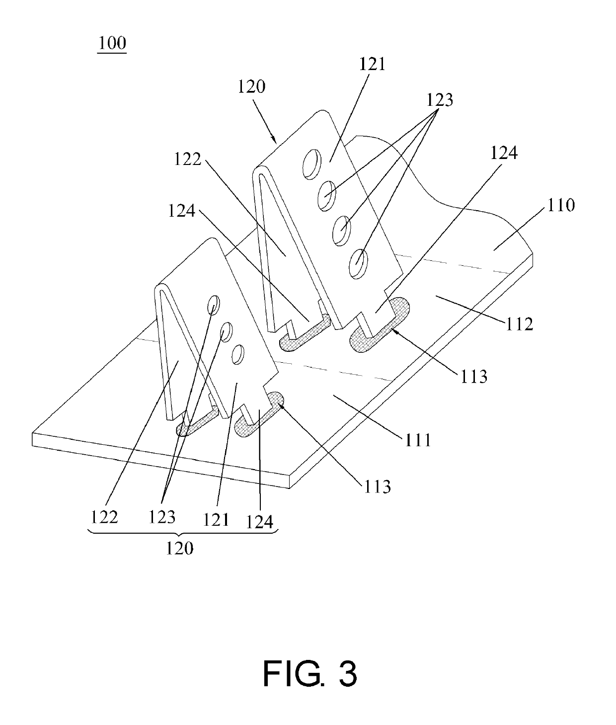
[0027]Specifically, each of the metal connection stand 120 includes a first connection piece 121 and a second connection piece 122, which are connected to each other and have an included angle. Each of end portions of the first connection piece 121 and the second connection piece 122 is electrically connected to the power outp...


PUM


Abstract

The invention discloses a circuit board output structure, which includes a power output section disposed on a circuit board and at least one metal connection stand electrically connected to the power output section. Each metal connection stand includes a first connection piece showing an included angle with respect to the circuit board. A plurality of connection holes for electrically connecting output wires are formed on the first connection piece. When it is required to change an output specification, the replacement can be more simple and convenient since the metal connection stand may be directly replaced without replacing the whole circuit board. Because the first connection piece has the included angle specified with respect to the circuit board, R angle and stress of the inserted output wires may be reduced to prevent the output wires from damage, detaching from the circuit board or having poor electrical contact after the assembly.

Description

CROSS-REFERENCE TO RELATED APPLICATION[0001]This application claims the priority benefit of China application serial no. 201720549798.4, filed on May 17, 2017. The entirety of the above-mentioned patent application is hereby incorporated by reference herein and made a part of this specification.BACKGROUND OF THE INVENTION1. Field of the Invention[0002]The invention relates to the technical field of power supply, and more particularly, to a power supply and a circuit board output structure thereof.2. Description of Related Art[0003]As shown by FIG. 1, in order to provide a plurality of output voltages, a power supply is generally provided with holes 111′ formed on a circuit board 110′ for inserting and soldering wires 130′. However, when it is required to change an output specification of the power supply, the holes 111′ and the wires 130′ on the circuit board 110′ can no longer be used. The circuit board 110′ and the wires 130′ need to be replaced by new ones and a layout of the cir...

Claims


Application Information

Patent Timeline
Patent Type & Authority Patents(United States)
IPC IPC(8): H01R12/51H01R12/52H05K1/18H05K1/02H01R12/53
CPCH01R12/515H01R12/53H05K1/0271H05K1/181H05K2201/10356H05K2201/1031H05K2201/10287H05K2201/10303
Inventor LU, SHAO-FENGWANG, CHUAN-KAI
Owner 3Y POWER TECH TAIWAN
Why Eureka
Try Eureka