Support structure of electrohydraulic apparatuses for irrigation systems, applicable to a buriable well for housing and protecting such electrohydraulic apparatuses

a technology of electrohydraulic apparatus and support structure, applied in the direction of artificial islands, containers, vehicles, etc., can solve the problems of not being able to exclude the possibility that even small movements of the apparatuses themselves can still bring them in contact with detritus or other dirt, and achieves the effect of being convenient, cost-effective and particularly functional

Active Publication Date: 2019-05-28
STIATTI ANNA +2
View PDF7 Cites 0 Cited by
  • Summary
  • Abstract
  • Description
  • Claims
  • Application Information

AI Technical Summary

Benefits of technology

[0006]The general purpose of the present invention is therefore to make a support structure of electrohydraulic apparatuses, in particular electrical and hydraulic apparatuses of irrigation systems, which is applicable to a buriable well for housing and protecting such electrohydraulic apparatuses so as to overcome the aforementioned drawbacks of the prior art in an extremely simple, cost-effective and particularly functional manner.
[0007]In particular, a purpose of the present invention is to make a support structure of electrohydraulic apparatuses for irrigation systems that is capable of avoiding, or at least reducing, the contact of such apparatuses with detritus or other dirt present on the ground.
[0008]Another purpose of the invention is to make a support structure of electrohydraulic apparatuses for irrigation systems that is capable of preventing possible undesired movements of such apparatuses when in use.

Problems solved by technology

In the case of solenoid valves, therefore, it is possible that detritus or other dirt present on the ground might compromise the correct operation thereof, requiring frequent maintenance interventions.
In other words, although these support structures, typically made in the form of grids, are configured to keep the apparatuses at a predetermined distance from the ground, it is not possible to exclude the possibility of even small movements of the apparatuses themselves still bringing them in contact with detritus or other dirt.

Method used


Image

  • Support structure of electrohydraulic apparatuses for irrigation systems, applicable to a buriable well for housing and protecting such electrohydraulic apparatuses
  • Support structure of electrohydraulic apparatuses for irrigation systems, applicable to a buriable well for housing and protecting such electrohydraulic apparatuses
  • Support structure of electrohydraulic apparatuses for irrigation systems, applicable to a buriable well for housing and protecting such electrohydraulic apparatuses

Examples


Embodiment Construction

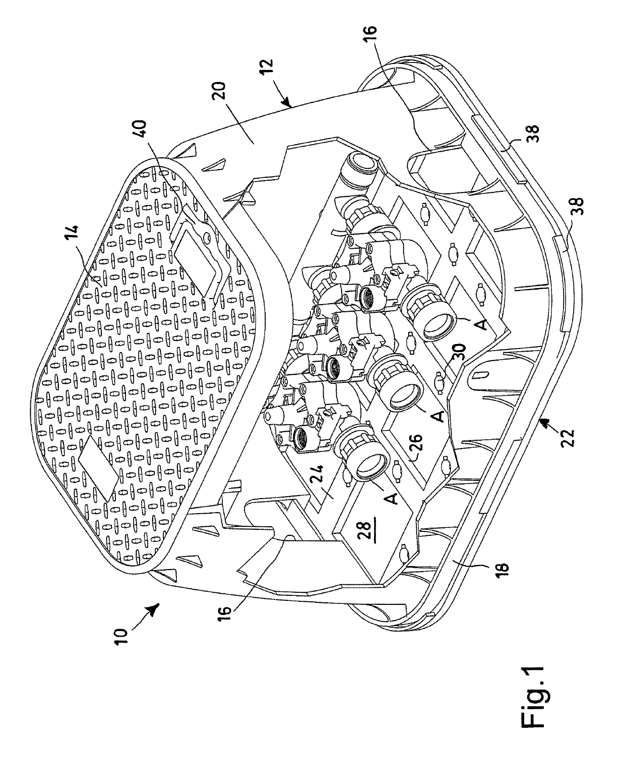
[0019]With reference in particular to FIG. 1, a buriable well for housing and protecting electrohydraulic apparatuses is shown, wholly indicated with reference numeral 10, to which a support structure of such electrohydraulic apparatuses according to the present invention can be applied.

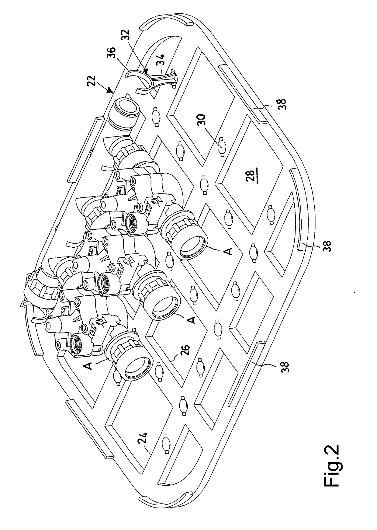
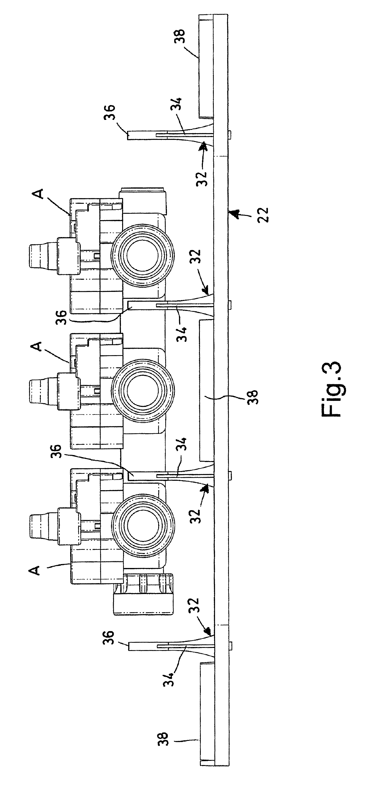
[0020]The well 10 comprises a main body 12 for housing the electrohydraulic apparatuses and a cover 14, applied onto an upper opening of such a main body 12. The main body 12 can also be provided with one or more further openings 16, provided on the base 18 and / or on the side walls 20 of the main body 12 itself, to allow the passage of the electrical and / or hydraulic supply lines of the apparatuses contained inside the well 10.

[0021]Both the main body 12 and the cover 14 are preferably made through injection molding of thermoplastic materials, although this does not exclude the use of other suitable materials depending on the intended use of the well 10. Generally, the base 18 of the main body 12 has...


PUM


Abstract

Support structures for electrohydraulic apparatuses in particular of electrical and hydraulic apparatuses of irrigation systems are disclosed. The support structure is configured to be applied to a buriable well for housing and protecting such electrohydraulic apparatuses. On predetermined portions of the support structure a plurality of holes are formed, and are adapted for receiving a corresponding plurality of support means configured to hold, preferably in a releasable manner, one or more electrohydraulic apparatuses. Also described is a buriable well for housing and protecting electrohydraulic apparatuses comprising at least one such support structure of electrohydraulic apparatuses.

Description

CROSS-REFERENCE TO RELATED APPLICATIONS[0001]This application claims the benefit of priority from Italian Utility Model Application No. 202015000034085 filed on Jul. 14, 2015, the contents of which are incorporated herein by reference.FIELD OF THE INVENTION[0002]The present invention refers to a support structure of electrohydraulic apparatuses, in particular electrical and hydraulic apparatuses of irrigation systems, applicable to a buriable well for housing such electrohydraulic apparatuses.BACKGROUND OF THE INVENTION[0003]To house solenoid valves, taps, hydrants and other apparatuses of an irrigation system that need to be buried, it is known to use wells having the purpose of allowing access to such apparatuses and protecting them from the soil and from detritus. Such wells normally comprise a main body for housing apparatuses, which has one or more lower openings, to allow the passage of the electrical and hydraulic supply lines of the apparatuses themselves, and an upper openi...

Claims


Application Information

Patent Timeline
Patent Type & Authority Patents(United States)
IPC IPC(8): A01G25/16B60W10/06E03B9/08H02G9/02A01G25/00E02D29/12E02D29/14E03B7/09H05K5/02E03B9/10E03B11/14H02G9/10B62K11/02B65D25/28B65D88/76
CPCB60W10/06A01G25/16B62K11/02B65D25/28B65D88/76E02D29/12E02D29/14E02D29/1454E03B7/095E03B9/08E03B9/10E03B11/14H02G9/02H02G9/10H05K5/0217A01G25/00Y10T137/6995B60W2300/36B62K2207/00B65D2525/283Y02A20/104Y02A20/00
Inventor STIATTI, ANNASTIATTI, MATTEO MARIASTIATTI, ALBERTO
Owner STIATTI ANNA
Why Eureka
Try Eureka