Digging equipment with relative improved hydraulic system

a technology of hydraulic system and digging equipment, which is applied in mechanical machines/dredgers, excavation, soil preservation, etc., can solve the problems of series damage, hydraulic component breaking or seizure, and reducing the lubricant properties of oil, etc., and achieves the effect of simple, cost-effective and functional

Active Publication Date: 2017-12-26
SOILMEC
View PDF16 Cites 0 Cited by
  • Summary
  • Abstract
  • Description
  • Claims
  • Application Information

AI Technical Summary

Benefits of technology

[0016]The purpose of the present invention is therefore to make digging equipment for making panels of deep diaphragms, in particular the hydraulic system of such digging equipment, which is able to solve the aforementioned drawbacks of the prior art in a simple, cost-effective and functional manner.

Problems solved by technology

Such contamination or pollution, even in small percentage concentrations, drastically reduces the lubricant properties of the oil and causes series damage such as breaking or seizure of the hydraulic components of the equipment.
This damage results in the loss of some hydraulic apparatuses for moving and for digging and, in the worst case scenario, makes it impossible to extract the immersed tool from the excavation.
The restoration of such functionalities is particularly expensive, requiring the replacement of the components and of the oil and causing long machine down times.
In the case in which the gaskets of the actuators of the digging tool are not perfectly efficient, or when the pipes and the relative fittings are not perfectly water-tight, or even due to problems deriving from incorrect compensation of the actuators (for example due to vibrations or pulsating phenomena induced by the digging, or due to a temperature variation), there can be penetration of the fluid of the excavation inside the hydraulic circuit of the digging equipment.
The critical points of the hydraulic circuit, where the penetration can occur most easily, are the sliding gaskets, the pipe fittings, which can loosen, or possible cracks and cuts that can appear on worn pipes.
The problem is particularly evident on the oil return lines towards the tank and on the draining lines of the rotary actuators, since in these lines the pressure inside the pipe can be lower than the hydrostatic pressure of the fluid in which they are immersed.
In high-pressure supply lines (delivery lines), on the other hand, there is the reverse problem, since oil can leak towards the environment outside the pipe, with consequent dispersion of oil in the excavation.
Since the flow rate of oil required for these apparatuses is very high, it would not be possible to supply it with a single pump and therefore multiple pumps are provided, each of which is dedicated just to a part of the apparatuses of the digging equipment.
It is thus clear that the entry of polluting agents in the circuit causes the pollution of the entire circuit and can block or damage any actuator or other hydraulic component of the digging equipment.
The damage and the consequent blocking of the functionalities of the actuators due to the pollution of the oil can be particularly serious if, during digging, with the tool immersed at great depth, the lifting apparatuses of the tool block.
If, for example, one of the malfunctioning actuators is the winch combined with recovering the cutter from the excavation, it becomes impossible to extract the digging tool using only the base machine and it becomes necessary to use a second support machine, which is not always available in the building site.
This means additional costs and very long down times.
In these cases, the power of the motor installed on the base machine is usually not sufficient to ensure the simultaneous operation of the apparatuses of the base machine and of the cutter.
This increase in the tail radius constitutes a limitation particularly in urban cutters, in other words in those cutters studied for use in built up areas where the maneuvering spaces are particularly small.
A further critical element of the solution that provides an external “power-pack”43 is the fact that the addition of a second external power motor inevitably causes an increase in consumption with respect to a solution dedicated to digging applications, with a single motor of suitable power.
Moreover, the external positioning of the “power-pack”43 with respect to the casing of the tower causes an increase in the noise emitted, which must be limited particularly in urban applications.
The increase in weight due to the mounting of the external “power-pack”43 increases the pressure on the soil of the tracks and this results in a limit in movement on the building site.
Finally, the accessibility of the “power-pack”43 is awkward since it is typically installed at a high level and the frequent necessary maintenance can be dangerous and not very easy.

Method used


Image

  • Digging equipment with relative improved hydraulic system
  • Digging equipment with relative improved hydraulic system
  • Digging equipment with relative improved hydraulic system

Examples


Embodiment Construction

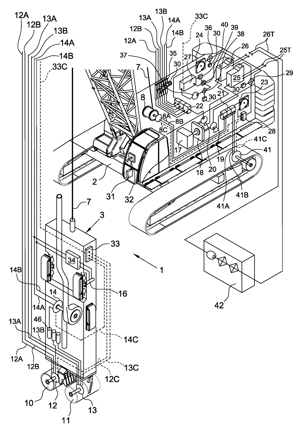
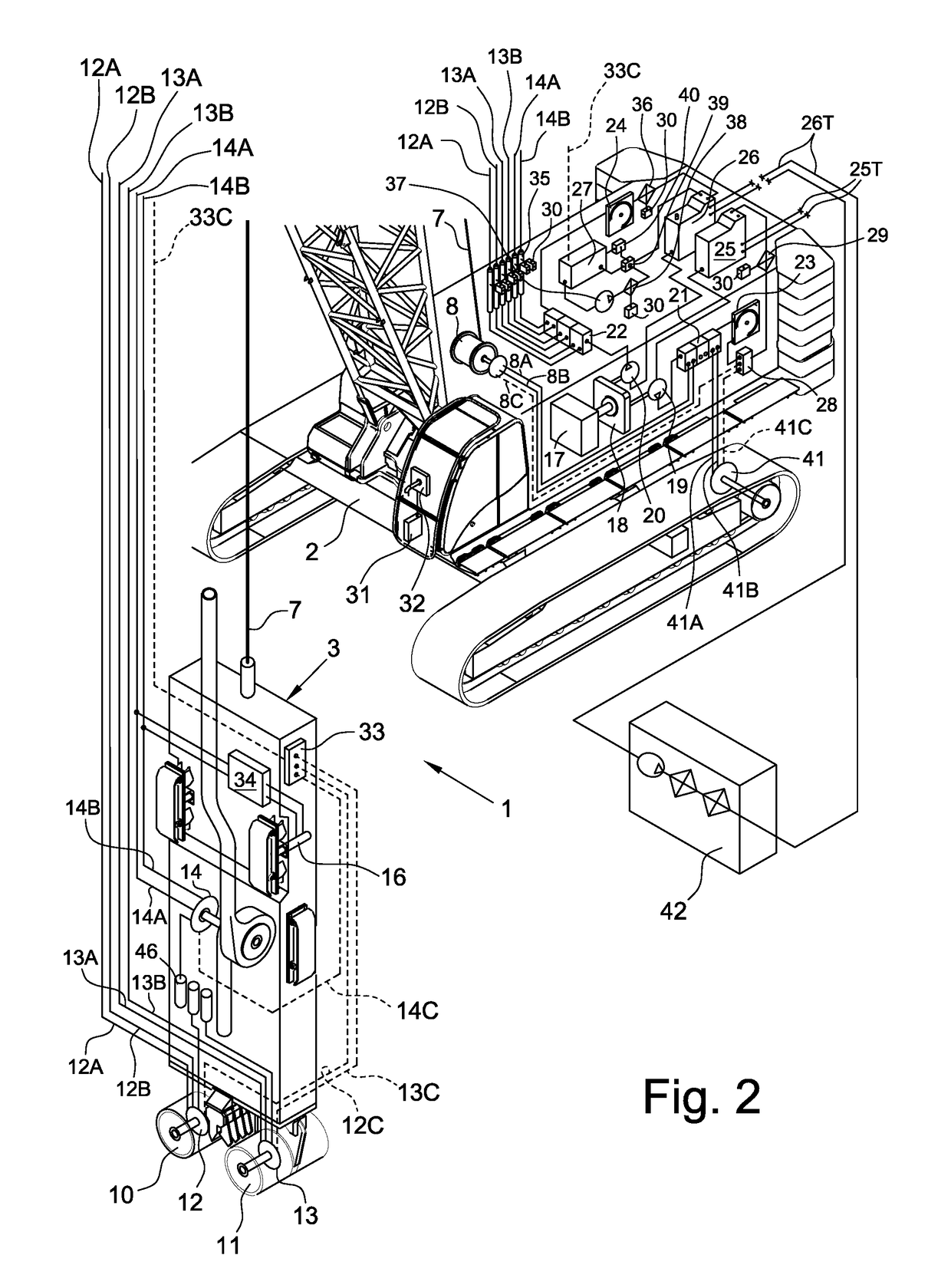
[0026]With reference in particular to FIG. 2, it is specified that the details and the elements that are similar, or have an analogous function, to those of the known digging equipment described earlier and illustrated in FIG. 1 are indicated with the same reference numerals.

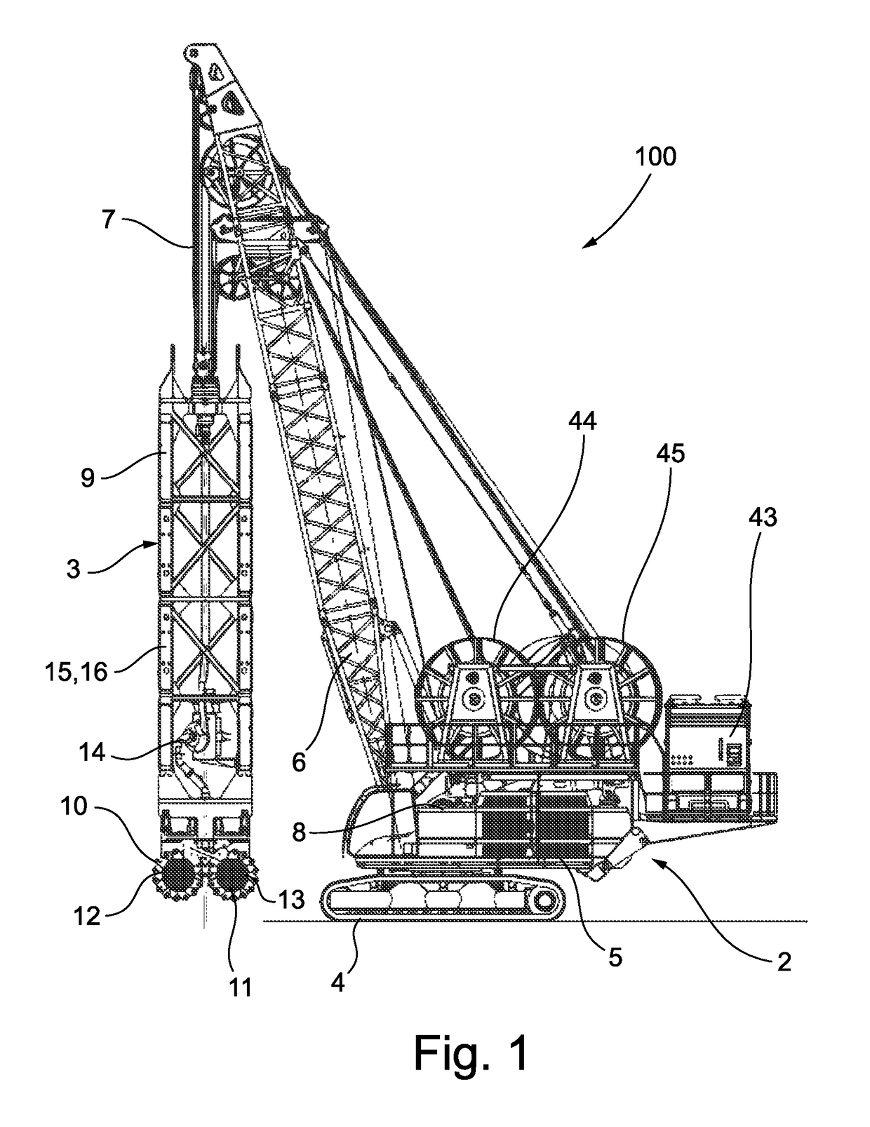
[0027]The digging equipment according to the present invention, wholly indicated with reference numeral 1, is made up of a base machine 2 and a crumbling or digging tool 3 operatively connected to the base machine 2. The base machine 2 comprises a tracked truck 4, a tower 5 rotating with respect to the tracked truck 4 and one arm 6, able to tilt and hinged to the tower 5, which supports the digging tool 3 through a suspending element 7 that is driven forwards by a winch. The suspending element 7 can be flexible, able to be directly wound or unwound through a winch 8. The winch 8 is installed on the base machine 2, inside or above the body, or fixed close to the winders 44 and 45, or furthermore directly connecte...


PUM


Abstract

The invention includes digging equipment having a self-propelled base machine provided with an arm that supports a digging tool. The digging tool is provided with a device for crumbling soil. The digging tool is operatively connected to the base machine through a suspending flexible element that can be wound or unwound by a winch arranged on the base machine. The base machine also includes a main power engine, to actuate all the hydraulic apparatuses of the digging equipment, and a hydraulic system consisting of two independent and separate hydraulic circuits (S; U). A first hydraulic circuit (S) is configured to control and supply the main service apparatuses of the base machine, including a movement apparatus for moving the digging tool. A second hydraulic circuit (U) is configured to control and supply the main digging apparatuses of the digging tool, including at least the actuators of the device for crumbling soil.

Description

CROSS-REFERENCE TO RELATED APPLICATIONS[0001]This application claims the benefit of Italian Patent Application No. MI2014A000492, filed Mar. 24, 2014.FIELD OF THE INVENTION[0002]The present invention refers to digging equipment for making deep diaphragm panels and, in particular, to the hydraulic system of such digging equipment. In greater detail, the present invention refers to digging equipment suitable for use in an urban environment with little spaces for maneuvering and for applications in which high power is required.BACKGROUND OF THE INVENTION[0003]In the field of foundations, in order to make impermeable or structural diaphragms, it is known to use digging equipment consisting of a base machine or “carrier”, like for example a tracked crane or a drilling machine, equipped with tracks, which supports and moves an immersion digging tool equipped with hydraulic apparatuses like, for example, a cutter. The base machine is positioned on the surface of the soil, from which the di...

Claims


Application Information

Patent Timeline
Patent Type & Authority Patents(United States)
IPC IPC(8): E02F3/20E21B7/02E02D3/12E02D17/13E02F9/22
CPCE02D3/126E02F3/205E21B7/02E02F9/2232E02F9/2292E02F9/226
Inventor CICCOTELLI, VALENTINO
Owner SOILMEC
Why Eureka
Try Eureka