
Oxidation intensifier device for indigo dyeing systems

a dyeing system and intensifier technology, applied in the direction of dyeing process, liquid/gas/vapor textile treatment, indefinite length material liquid/gas/vapor treatment, etc., can solve the problem of loss of yarn corresponding to said length, difficult control of the system, high variable parameters, etc. problem, to achieve the effect of facilitating the application

Active Publication Date: 2021-01-05
KARL MAYER STOLL R&D GMBH
View PDF15 Cites 0 Cited by
  • Summary
  • Abstract
  • Description
  • Claims
  • Application Information

AI Technical Summary

Benefits of technology

This patent describes an oxidation intensifier device for indigo dyeing systems that can reduce waste and energy consumption by reducing the length of yarn that needs to be exposed to air for oxidation between dyeing processes. The device also allows for a longer air / yarn interchange time without increasing the size of the dyeing system. The device's construction makes it easy to apply to standard oxidation equipment of dyeing systems without changing the yarn's path.

Problems solved by technology

In practice, however, each manufacturer uses different parameters from its competitors and therefore these parameters are highly variable.
This length of the yarn, with the addition of minor amounts due to the drawing in other parts of the system (pre-treatment vats and final washings of the yarn, sizing machine, etc.), actually reaches a total of about 500 / 600 metres, which contributes to making the control of the system more difficult.
In addition, at each batch change, the amount of yarn corresponding to said length must be considered lost, since it is not dyed uniformly because of problems relating to the beginning of the new batch.
This system has however proved inefficient both due to the non-uniformity of the air flow between the different dyeing vats, and due to the large load losses of the air flow itself.
This feature of leuko, together with the continuous demands of increase of the operating speed of dyeing systems, has further highlighted the limitations and the inadequacy of current oxidation intensification devices as described above.
However, none of these devices is provided with equipment capable of dynamically adjusting in real time the air speed and flow rate to be blown onto the warp thread.

Method used


Image

  • Oxidation intensifier device for indigo dyeing systems
  • Oxidation intensifier device for indigo dyeing systems
  • Oxidation intensifier device for indigo dyeing systems

Examples


Embodiment Construction

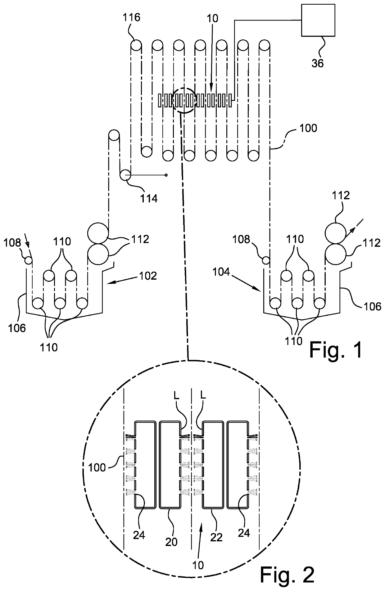
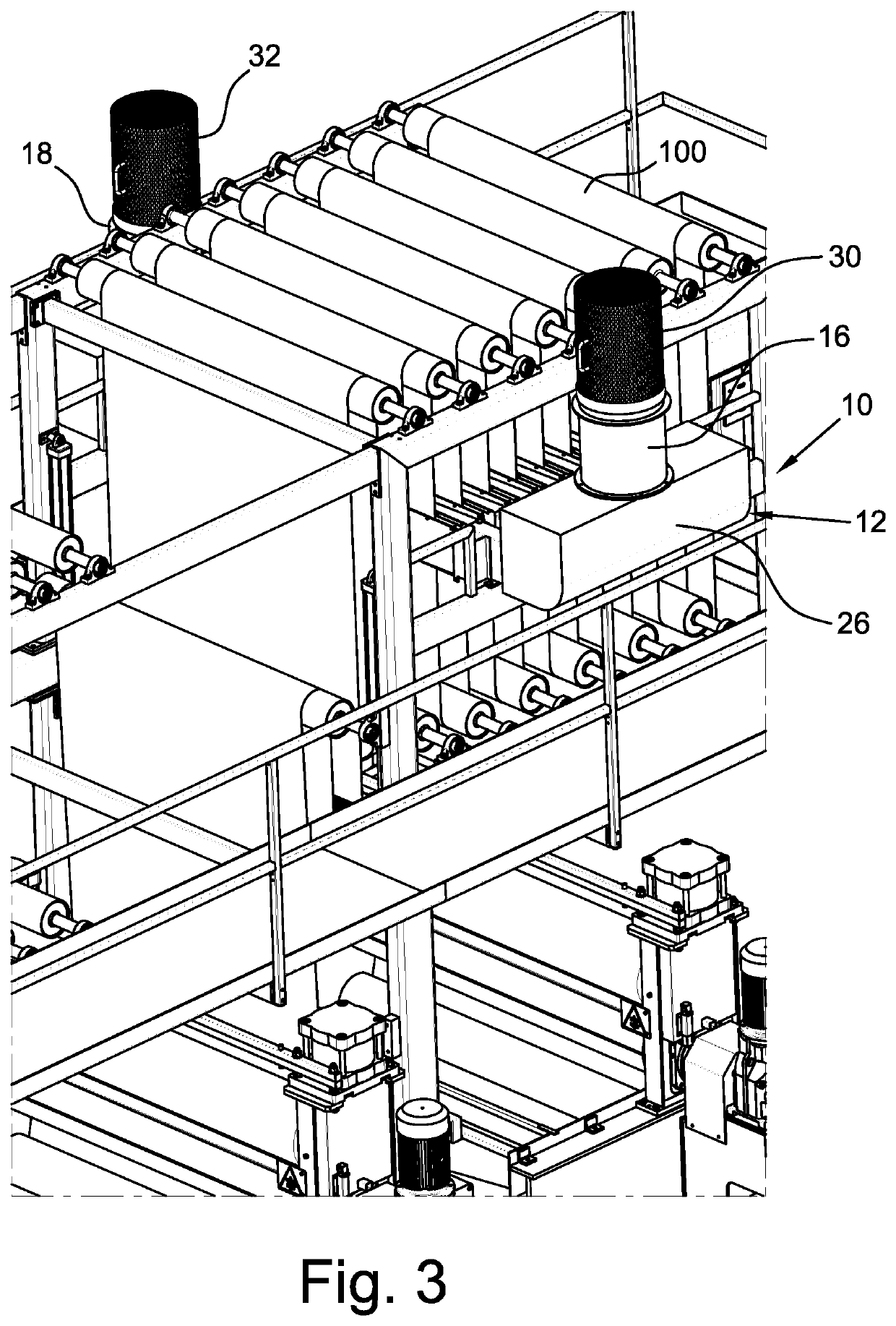
[0034]With reference in particular to FIG. 1, the oxidation intensifier device according to the present disclosure, generally indicated with reference numeral 10, is installed in the space between two dyeing / squeezing assemblies 102 and 104 of a continuous dyeing system for threads, in particular a system which operates according to the open width dyeing system. Each of the dyeing / squeezing assemblies 102 and 104 comprises a respective impregnation vat 106 in which a warp thread 100, which advances in the direction of the arrows indicated in FIG. 1, is introduced in a dye bath. The dye bath may consist, for example, of an alkaline solution of indigo dye.

[0035]The warp thread 100 arrives in each vat 102 and 104 passing over a respective guide roller 108 and is then immersed in the vat itself by twisting on a plurality of return rollers 110. At the exit of each vat 102 and 104, the warp thread 100 undergoes a squeezing by passing between a pair of squeezing rollers 112.

[0036]The oxida...


PUM

PropertyMeasurementUnit
angleaaaaaaaaaa
lengthaaaaaaaaaa
lengthaaaaaaaaaa

Abstract

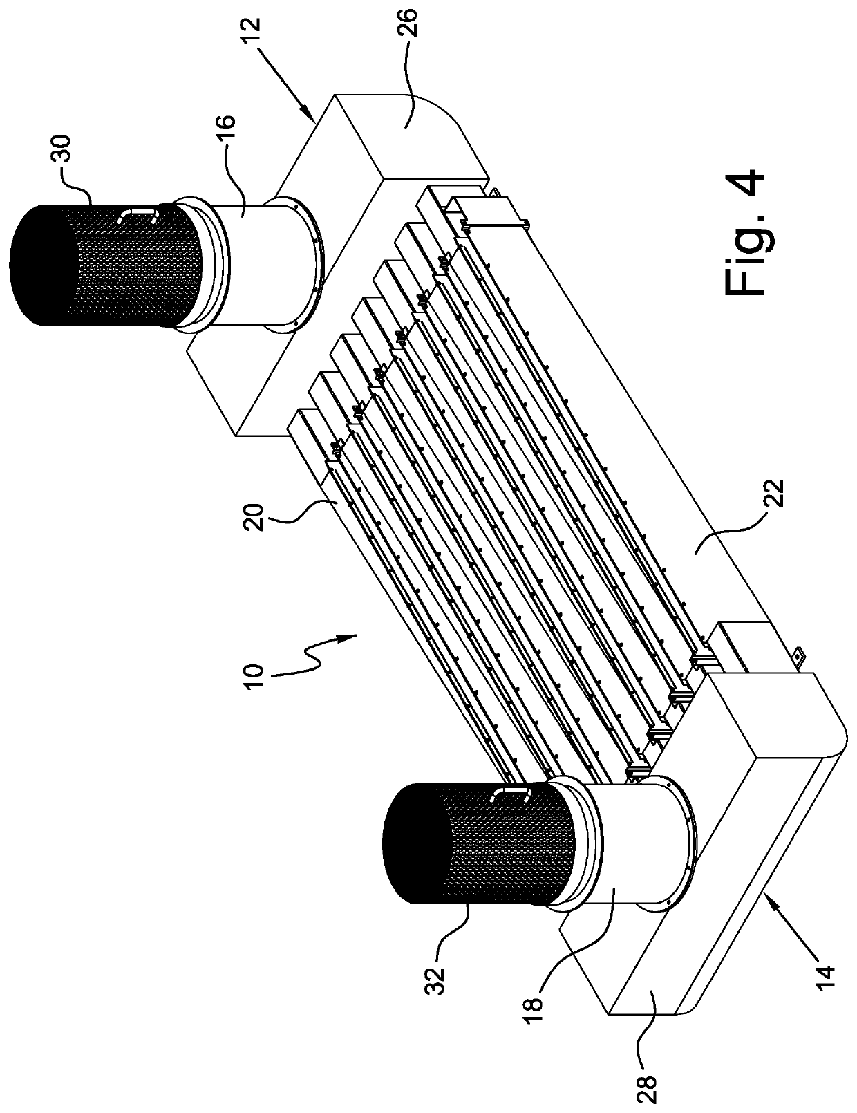
An oxidation intensifier device for a continuous dyeing system for dyeing a warp thread, the device arranged for being mounted in the oxidation assembly of the dyeing system and comprises two blowing assemblies having a substantially identical shape and opposed one another, each blowing assembly is provided with at least one respective fan and, downstream of such a fan, with a respective plurality of convergent conduits arranged along development directions that are parallel and transversal to the feeding direction of the warp thread, the convergent conduits of a first blowing assembly converge in a opposite direction with respect to the convergence direction of the convergent conduits of the opposite blowing assembly, each convergent conduit is configured to face parallel to a single lap of the warp thread moving inside the dyeing system and is provided with a plurality of longitudinal slots oriented along the same development direction of the respective convergent conduit, where each fan is hydraulically connected to the plurality of convergent conduits of the respective blowing assembly and is configured to convey air towards the plurality of longitudinal slots, so that a plurality of opposite air laminar flows is generated, which generate a plurality of turbulences adapted to facilitate the oxidation process of the dyed warp thread on both its surfaces.

Description

TECHNICAL FIELD[0001]The present disclosure relates to a device applicable to continuous flat dyeing systems for dyeing warp yarns for denim fabrics, with indigo dye, to intensify and complete the oxidation of such yarns after each single dye.BACKGROUND[0002]As is known, denim is the fabric used for making jeans and sportswear articles in general, and is the quantitatively most produced fabric in the world. Consequently, indigo is the most consumed dye in the world.[0003]Classic denim, or fabric for jeans, is manufactured by weaving previously dyed cotton threads. In particular, only the warp is dyed continuously with indigo, while the weft is used raw. Typically and traditionally, the dyeing of warp yarns for denim fabrics is carried out in open vat and at low temperature, using indigo as the dye, with both the so-called “rope” system, in which the yarn is twisted into multiple longitudinal ropes of some hundreds of yarns, and with the so-called “open width” system, in which the ya...

Claims


Application Information

Patent Timeline
Patent Type & Authority Patents(United States)
IPC IPC(8): D06B5/06D06B19/00D06P1/22D06P3/60
CPCD06B5/06D06B19/0017D06P1/228D06P3/6025
Inventor RONCHI, FRANCESCO
Owner KARL MAYER STOLL R&D GMBH
Learn More