Air conditioning tower

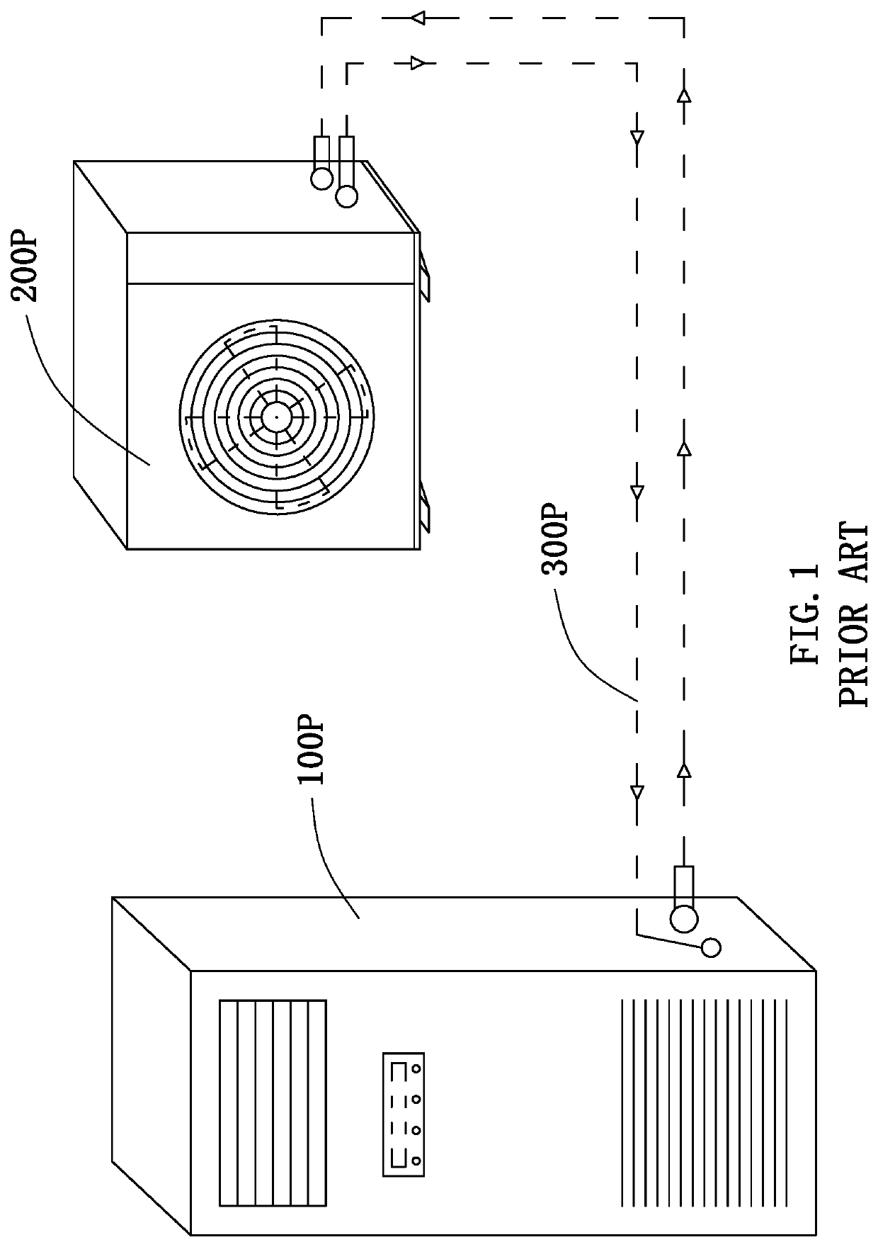
a technology of air conditioning tower and air conditioner, which is applied in the direction of indirect heat exchangers, lighting and heating apparatus, heating types, etc., can solve the problems of difficult installation and maintenance of substantial amount of energy lost or wasted during refrigerant circulation, and low efficiency of the evaporator used in split-type air conditioning systems

Active Publication Date: 2020-06-16
WONG LEE WA
View PDF2 Cites 0 Cited by
  • Summary
  • Abstract
  • Description
  • Claims
  • Application Information

AI Technical Summary

Benefits of technology

[0007]Another objective of the present invention is to provide an air conditioning tower comprising a plurality of water collection basins which are capable of effectively and evenly guiding cooling water to perform heat exchange with heat exchanging pipes.
[0008]Another objective of the present invention is to provide an air conditioning tower which can be easily and conveniently installed on a wall structure. Notably, the air conditioning tower of the present invention may stand on a ground surface so that mounting procedures of the present invention can be kept to the minimum.

Problems solved by technology

There are several disadvantages associated with the above-mentioned split-type air conditioning system.
The efficiency of the evaporator used in the split-type air conditioning system is also very low.
Second, although a split-type air conditioning system may have some advantages in some circumstances, the use of ducts 300P in connecting the indoor air conditioning unit 100P and the outdoor compressor unit 200P means that a substantial amount of energy is lost or wasted during circulation of refrigerant.
Third, since the indoor air conditioning unit 100P and the outdoor compressor unit 200P are located in different parts of a premises, this makes installation and maintenance of the split-type air conditioning system very difficult.
In some situations, technicians may not be able to access the outdoor compressor unit 200P because it may be blocked by some other obstacles.

Method used


Image

  • Air conditioning tower
  • Air conditioning tower
  • Air conditioning tower

Examples


Embodiment Construction

[0041]The following detailed description of the preferred embodiment is the preferred mode of carrying out the invention. The description is not to be taken in any limiting sense. It is presented for the purpose of illustrating the general principles of the present invention.

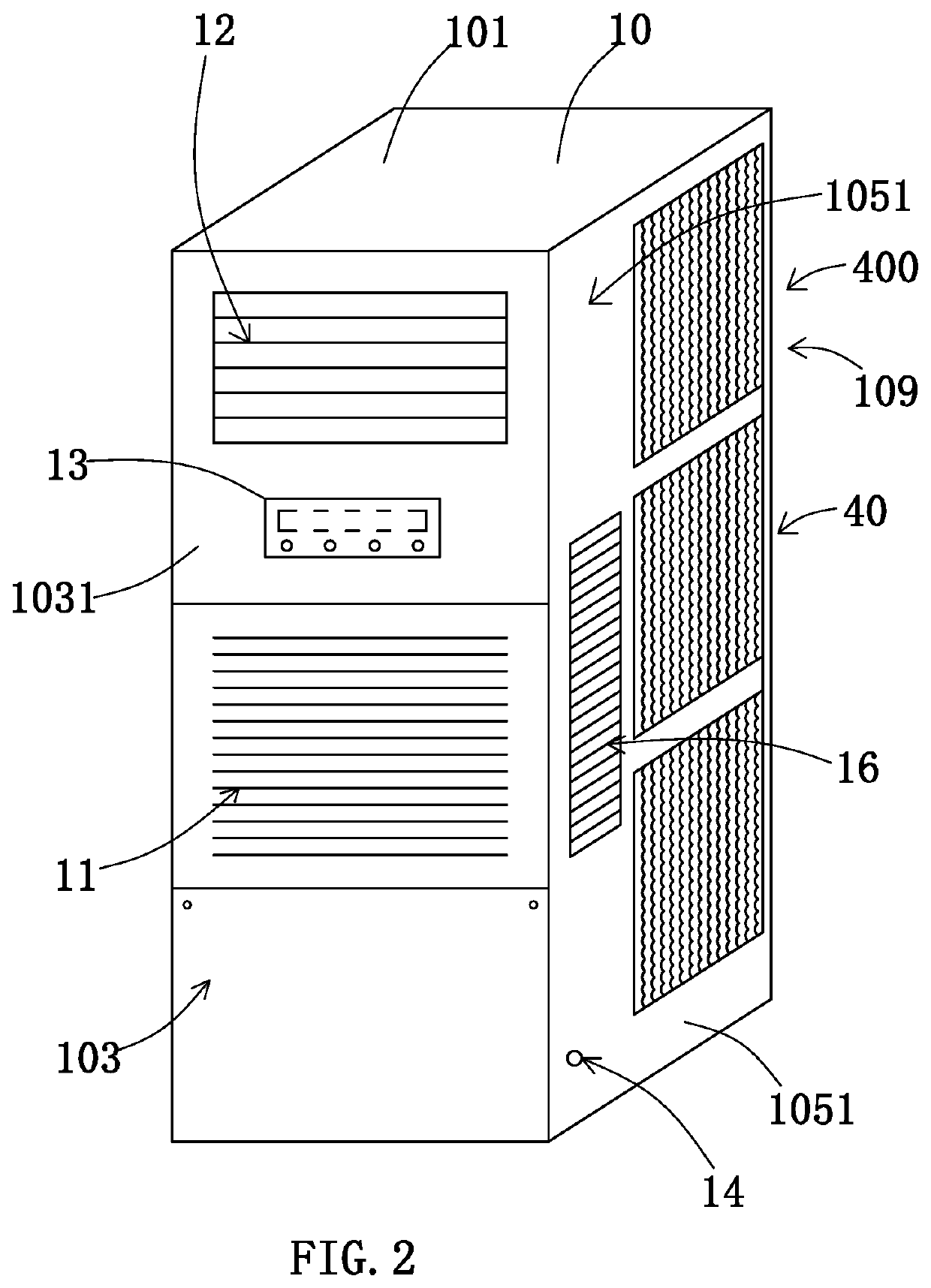
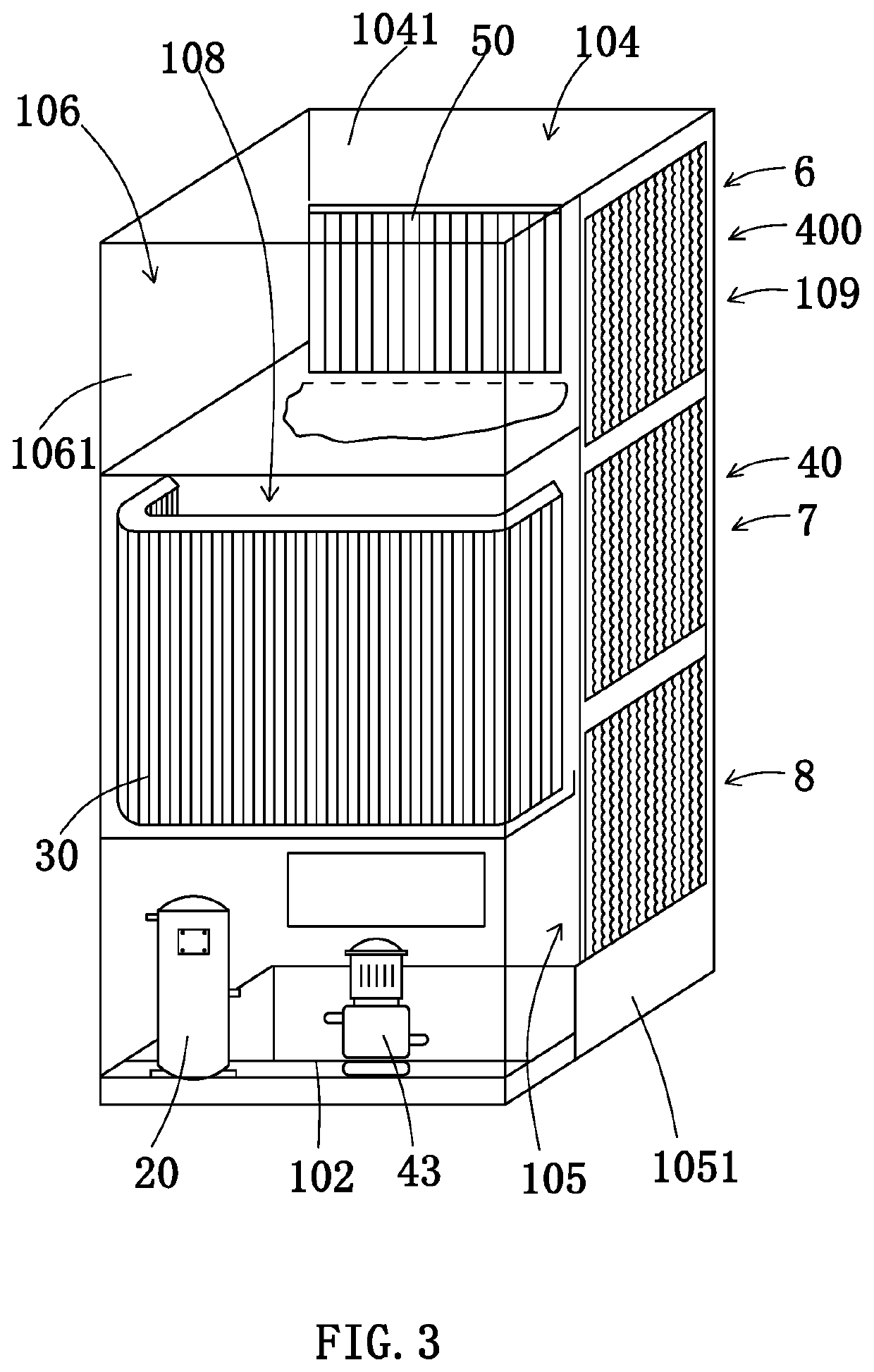
[0042]Referring to FIG. 2 to FIG. 4, FIG. 5A, FIG. 5B and FIG. 6 to FIG. 11 of the drawings, an air conditioning tower according to a preferred embodiment of the present invention is illustrated. Broadly, the air conditioning tower comprises a tower casing 10, a compressor 20 having a compressor outlet 21 and a compressor inlet 22, a heat exchanger 30 having a heat exchanging outlet 31 and a heat exchanging inlet 32, an evaporative cooling system 400, and a centrifugal fan 50. A predetermined amount of refrigerant is circulating between these components, preferably through connecting pipes or heat exchanging pipes which is described below.

[0043]The tower casing 10 has a front portion 103, a rear portion 104, a f...


PUM

PropertyMeasurementUnit
flow rateaaaaaaaaaa
temperatureaaaaaaaaaa
heightaaaaaaaaaa

Abstract

An air conditioning tower includes a tower casing, a compressor provided in the tower casing, a heat exchanger provided in the tower casing and connected to the compressor, an evaporative cooling system which includes at least one multiple-effect evaporative condenser, and a centrifugal fan. The multiple-effect evaporative condenser includes a pumping device, a first cooling unit, a second cooling unit, and a bottom water collecting basin. The first cooling unit includes a first water collection basin, a plurality of first heat exchanging pipes, and a first fill material unit. The second cooling unit includes a second water collection basin, a plurality of second heat exchanging pipes, and a second fill material unit.

Description

BACKGROUND OF THE PRESENT INVENTIONField of Invention[0001]The present invention relates to an air conditioning system, and more particularly to an air conditioning tower which has a single structure and provides a cooling effect to a large area without using extensive piping network.Description of Related Arts[0002]As shown in FIG. 1 of the drawings, a conventional split-type air conditioning system usually comprises an indoor air conditioning unit 100P and an outdoor compressor unit 200P. The indoor air conditioning unit 100P is located indoor while the outdoor compressor unit 200P is positioned in outdoor environment. They are connected by a plurality of ducts 300P.[0003]There are several disadvantages associated with the above-mentioned split-type air conditioning system. First, a conventional split-type air conditioning system must involve circulation of refrigerant between the indoor air conditioning unit 100P and the outdoor compressor unit 200P. The refrigerant carries heat ...

Claims


Application Information

Patent Timeline
Patent Type & Authority Patents(United States)
IPC IPC(8): F28D5/02F24F1/02F28F19/02F28D21/00F28F25/00F24F1/029F24F1/0323F24F1/0328F24F1/0358
CPCF28D5/02F28F19/02F24F1/02F28F2025/005F28D21/0017F24F1/0328F24F1/029F24F1/0323F24F1/0358
Inventor WONG, LEE WA
Owner WONG LEE WA
Why Eureka
Try Eureka