Edge Metal System

a metal system and edge technology, applied in the direction of roof coverings, roofs, constructions, etc., can solve the problems of metal springs transferring too much tension to the face of metal coverings, appearance is not aesthetically pleasing, etc., to achieve and easy and convenient installation and/or use

Active Publication Date: 2018-08-16
GARLAND INDS
View PDF2 Cites 0 Cited by
  • Summary
  • Abstract
  • Description
  • Claims
  • Application Information

AI Technical Summary

Benefits of technology

[0012]In another and / or alternative non-limiting aspect of the present invention, the locking flange of the base anchor is generally designed to be positionable about parallel to the sidewall of the building; however, this is not required. The locking flange can be integrally formed with the base anchor; however, this is not required. Similarly, the engagement flange, base anchor, locking flange, or any combination thereof can be formed in a one-piece construction; however, this is not required. In one non-limiting configuration, the locking flange is provided and / or positioned opposite the engagement flange; however, this is not required. The locking flange can be designed to include one or more holes and / or apertures for the purpose of receiving one or more fasteners (e.g., screws, nails, bolts, clips, pins, etc.); however, this is not required. The one or more holes and / or apertures (when used) are not limited in size and / or shape. In one non-limiting configuration, the diameter of the one or more holes and / or apertures (when used) can be from about 1 / 16 inches to about 2 inches, more typically from about ⅛ inches to about 1.75 inches, and more typically from about ¼ inches to about 1 inch. The one or more holes and / or apertures can be designed to facilitate one or more fasteners as said one or more fasteners are secured into a nailer and / or sidewall of a building. In another and / or alternative non-limiting configuration, the locking flange can include one or more perforated portions wherein the perforated portions are designed to be easily and conveniently removed from the locking flange so as to facilitate in using the one or more fasteners with the locking flange; however, this is not required. Typically, the one or more holes and / or apertures are provided on a portion of the locking flange behind which a nailer is provided; however, this is not required. As such, the locking flange can facilitate the attachment of the roof edging system to a building. In another and / or alternative non-limiting configuration, the one or more holes and / or apertures can be provided on a first portion of the locking flange which has a greater thickness than a second portion of the locking flange; however, this is not required. The thickened portion of the locking flange can be provided for the purpose of improving the strength and rigidity properties of the locking flange, thereby improving the overall strength and rigidity of the roof edging system.
[0025]In operation, one non-limiting method of easily and conveniently installing and / or using a roof edging system as described above can comprise one or more steps. Initially, the compression system can be attached to the mounting surface of the engagement flange. Then, the base anchor can be attached to the sidewall of a building by securing one or more fasteners through one or more holes and / or apertures in the locking flange. Optionally, a base anchor extender can then be connected to the locking flange of the base anchor and further connected to the sidewall of the building and / or nailer by one or more fasteners; however, this is not required. Optionally, one or more splice plates can be positioned over the base anchor and compression system; however, this is not required. Subsequently, the fascia cover can be positioned over the splice plate (when used), base anchor, and base anchor extender (when used) such that the engagement end of the first vertical portion of the fascia cover is positioned at or near the engagement end of the locking flange, and the engagement end of the second vertical portion of the fascia cover is positioned at or near the second angled portion of the engagement flange. The fascia cover can be cause to move downwardly, thereby compressing the compression portion of the compression system. As the compression portion is compressed, the engagement end of the first vertical portion of the fascia cover and the engagement end of the second vertical portion of the fascia cover can simultaneously snap onto and hook the engagement end of the locking flange and the engagement end of the second vertical portion, respectively. As the fascia cover is released, the compression portion of the compression system can expand and extend upwardly towards its biased position, thereby taking up any slack between the base anchor and the fascia cover.
[0026]In operation, another and / or alternative non-limiting method of easily and conveniently installing and / or using a roof edging system as described above can comprise one or more steps. Initially, the compression system can be attached to the top surface of the engagement flange. Then, the base anchor can be attached to the sidewall of a building by securing one or more fasteners through the holes and / or apertures of the locking flange to the sidewall of the building and / or nailer. Optionally, a base anchor extender can then be connected to the locking flange of the base anchor and further connected to the sidewall of the building and / or nailer by one or more fasteners; however, this is not required. Optionally, one or more splice plates can be positioned over the base anchor and compression system; however, this is not required. Subsequently, the engagement end of the first vertical portion of the fascia cover can be positioned around the engagement end of the locking flange, thereby “hooking” the locking flange. The fascia cover can then be rotated and / or pivoted in a forward direction over the roof of the building such that the engagement end of the second vertical portion of the fascia cover is positioned at or near the second angled portion of the engagement flange. The fascia cover can then be caused to move downwardly, thereby compressing the compression portion of the compression system against the mounting surface of the engagement flange, and engaging the engagement end of the second vertical portion of the fascia cover to the second angled portion of the engagement flange. As the fascia cover is released, the compression portion of the compression system can expand and extend upwardly towards its biased position, thereby taking up any slack between the base anchor and the fascia cover.

Problems solved by technology

However, such metal springs can transfer too much tension to the face of the metal covering.
Such an appearance is not aesthetically pleasing.

Method used


Image

  • Edge Metal System
  • Edge Metal System
  • Edge Metal System

Examples


Embodiment Construction

[0044]Referring now to the drawings, wherein the showings are for the purpose of illustrating at least one non-limiting embodiment of the invention only and not for the purpose of limiting the invention, FIGS. 1-11 illustrate various non-limiting roof edging systems in accordance with the present invention.

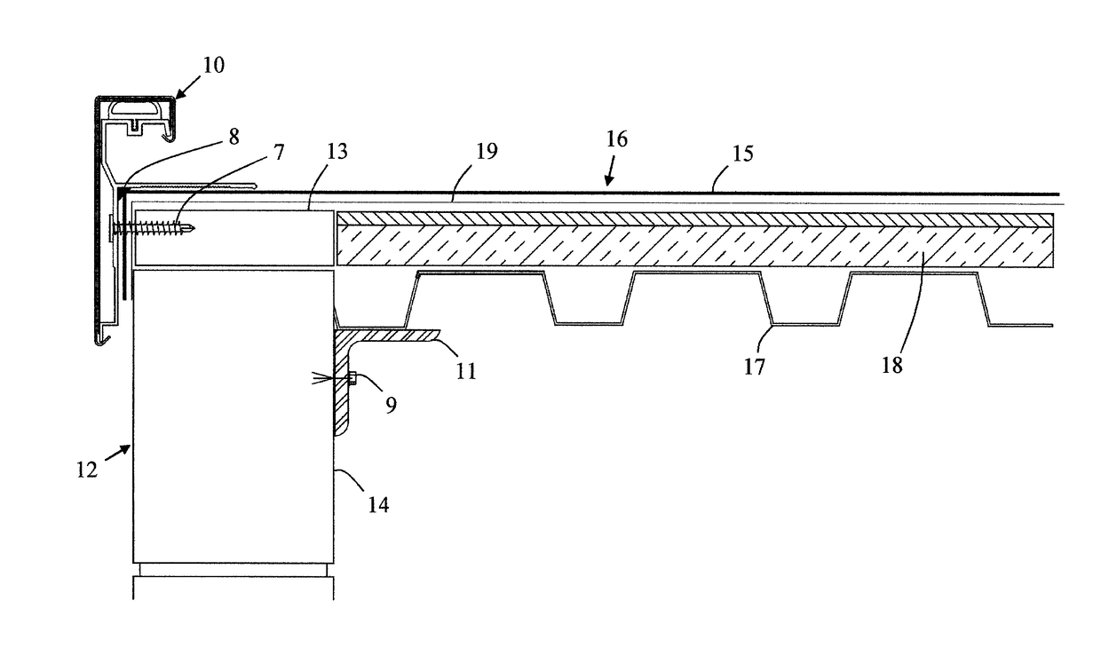
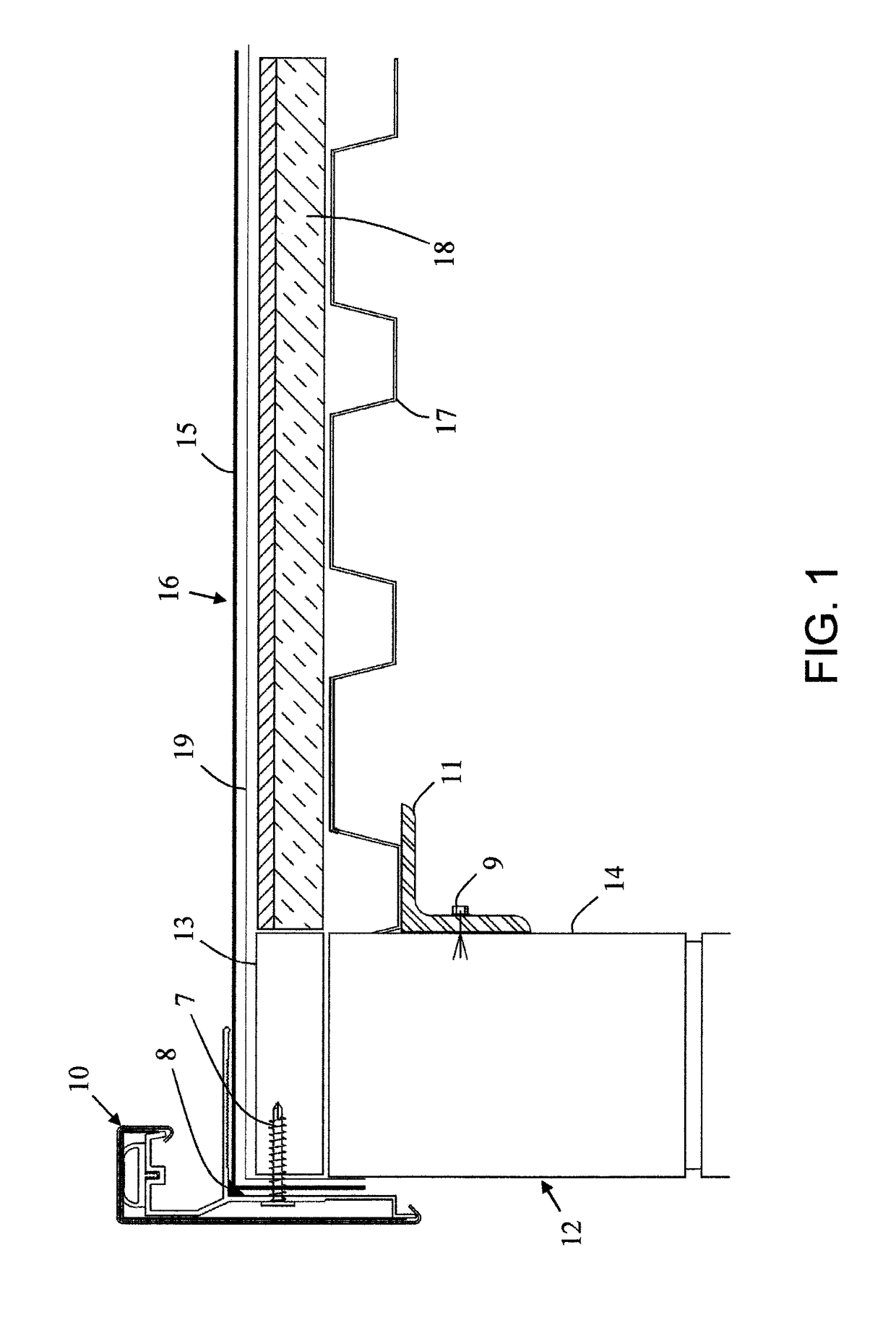
[0045]Referring now to FIG. 1, there is illustrated a roof edging system 10 connected to a building 12 having a sidewall 14 and a roof 16. One non-limiting roof 16 of building 12 includes multiple layers, such as, for example, a metal deck 17, insulation 18, base ply 19, and / or a roofing membrane 15. A bracket 11 can be used to support the one or more components of the roof 16 at or near the sidewall 14. A fastener 9 (e.g., bolt, screw, nail, clip, etc.) can be used to secure the bracket 11 to the sidewall 14. However, other or alternative connection means can be used (e.g., adhesives, etc.). Generally, roofing membrane 15 covers one or more components of the roof 16 and extends o...


PUM


Abstract

A roof edging system that includes a base anchor, a fascia cover, and a compression system that is used to provide compression thereby, allowing the fascia cover to snap into place on the base anchor.

Description

[0001]The present invention is a continuation of U.S. patent application Ser. No. 15 / 434,460 filed Feb. 16, 2017, which is incorporated herein by reference.[0002]The present invention relates to roof edging systems, particularly to a roof edging system that includes a compression system, and more particularly to a roof edging system that includes a compression system that is capable of compressing so as to allow a cap to engage a base anchor and be snapped or otherwise secured into place.BACKGROUND ON THE INVENTION[0003]Many types of building have flat roofs with exposed roof edges that must be sealed in order to prevent water from leaking into the interior of the building. The roofs on buildings of this type include adhered or mechanically attached single-ply roofs and built-up or modified roof systems, among others. In order to effectively seal the roofs of these buildings, many different roof edging systems, such as fascia covers and copings, have been developed which cooperate w...

Claims


Application Information

Patent Timeline
Patent Type & Authority Applications(United States)
IPC IPC(8): E04D13/158E04D13/16
CPCE04D13/158E04D13/1643E04D13/15
Inventor ARNOLD, KEVINDIAMOND, THOMAS G.HENSLEY, RANDYJONES, GEORGELORD, TRAVIS DONALDWAHL, ZACHARY MICHAELRESSO, FRANK V.
Owner GARLAND INDS
Why Eureka
Try Eureka