Rollout tray mounting system for cabinet

a cabinet and tray technology, applied in the field of furniture, can solve the problems of loosening of the dowels, difficult to attach via screws to the slide member, and difficult to attach round dowels, and achieve the effect of convenient and convenient installation

Active Publication Date: 2009-06-16
TENN TEX PLASTICS
View PDF30 Cites 2 Cited by
  • Summary
  • Abstract
  • Description
  • Claims
  • Application Information

AI Technical Summary

Benefits of technology

[0010]In embodiments of the present invention, the base may include a base panel, a vertically elongated first lip and / or a vertically elongated second lip. The base panel and / or first and second lips may include one or more apertures that facilitate mounting the connector to the wall of a cabinet. In embodiments of the invention, the first and second lips may comprise the entirety of the base. The connector may also include one or more reinforcing ribs that extend between the first mounting panel and the second mounting panel, and may further include an alignment slot that may facilitate aligning the connector during installation. In certain embodiments, the connector is a unitary structure formed of a polymeric material.
[0014]An additional aspect of the present invention is directed to methods of installing a cabinet drawer mounting member along with an associated connector within a face-frame cabinet in a manner that allows the drawer mounting hardware to be easily and conveniently installed so as to properly align the drawer within the cabinet. Pursuant to these methods the connector is attached to a wall of the cabinet so that the bottom surface of the connector contacts the floor of the cabinet, and the mounting member is attached to the connector such that the bottom of the mounting member is positioned at a predetermined height above the bottom of the mounting member. A slide member is attached to the mounting member and the installation may be completed by slidably installing the drawer on the slide member.

Problems solved by technology

One issue with this system is the attachment of the round dowel to the slide member.
Because the dowel is typically relatively small (about 0.320 inch in diameter) and is round, it can be somewhat difficult to attach via screws to the slide member, as the dowel tends to spin undesirably during attachment.
Also, the round dowels tend to slide out of the holes in the vertical mounting member during shipping and / or use of the cabinet.
Moreover, the screws tend to “back-out” of the holes in the dowels, which can loosen the dowels or even cause them to become disconnected from the slide members.
However, in many instances glue and / or staples used to attach the front wall frame to the side walls are present in the corners.
Consequently, it may be difficult in some instances to position the mounting member flush against the corner.
Also, the relatively short length of the mounting members ordinarily requires the installer to position the mounting members precisely so that the holes of facing mounting members are at substantially the same height; otherwise, the tray or drawer may not be level when mounted.

Method used


Image

  • Rollout tray mounting system for cabinet
  • Rollout tray mounting system for cabinet
  • Rollout tray mounting system for cabinet

Examples


Embodiment Construction

[0046]The present invention will now be described more fully hereinafter, in which preferred embodiments of the invention are shown. This invention may, however, be embodied in different forms and should not be construed as limited to the embodiments set forth herein. Rather, these embodiments are provided so that this disclosure will be thorough and complete, and will fully convey the scope of the invention to those skilled in the art. In the drawings, like numbers refer to like elements throughout. Thicknesses and dimensions of some components may be exaggerated for clarity.

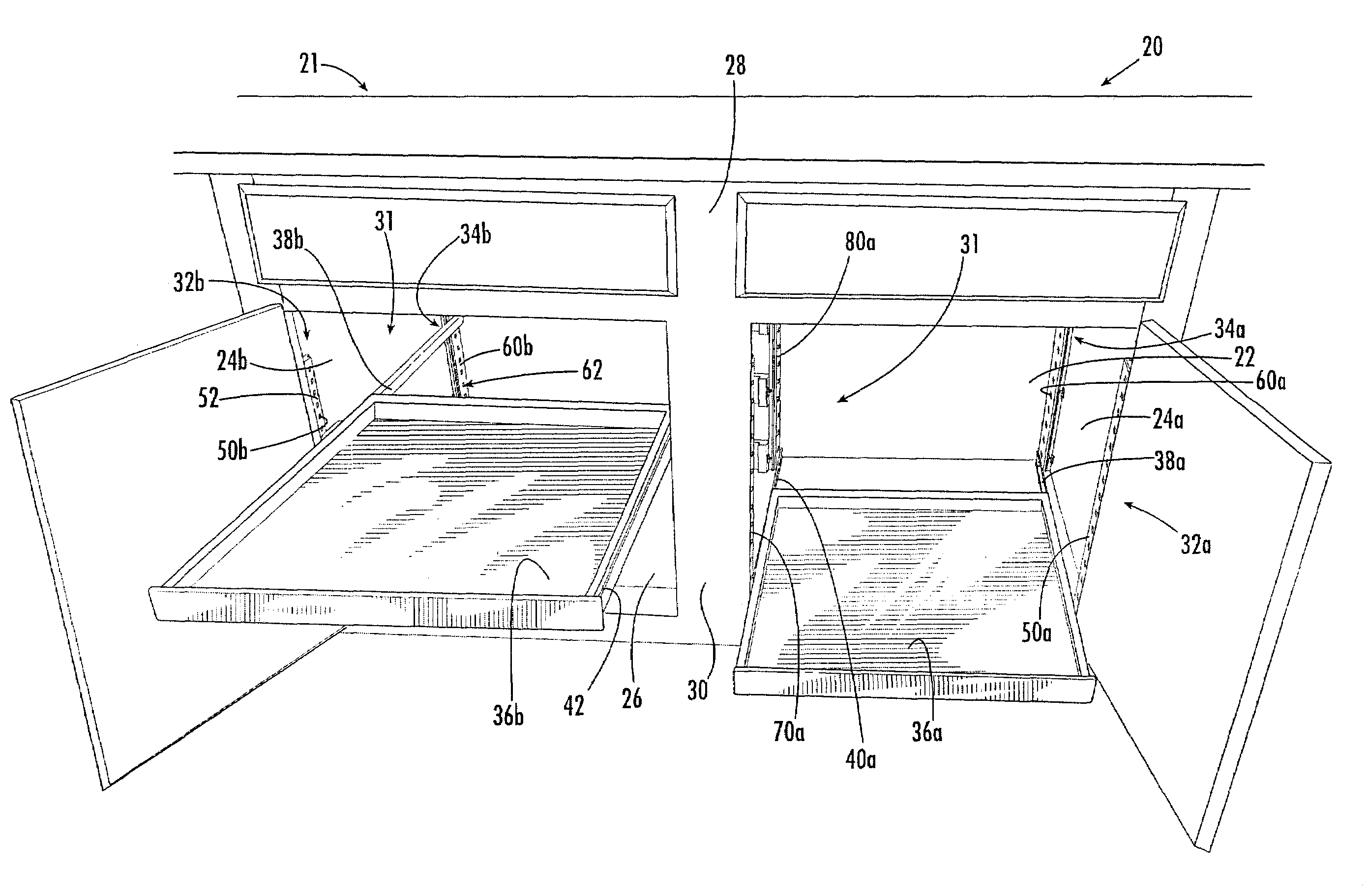
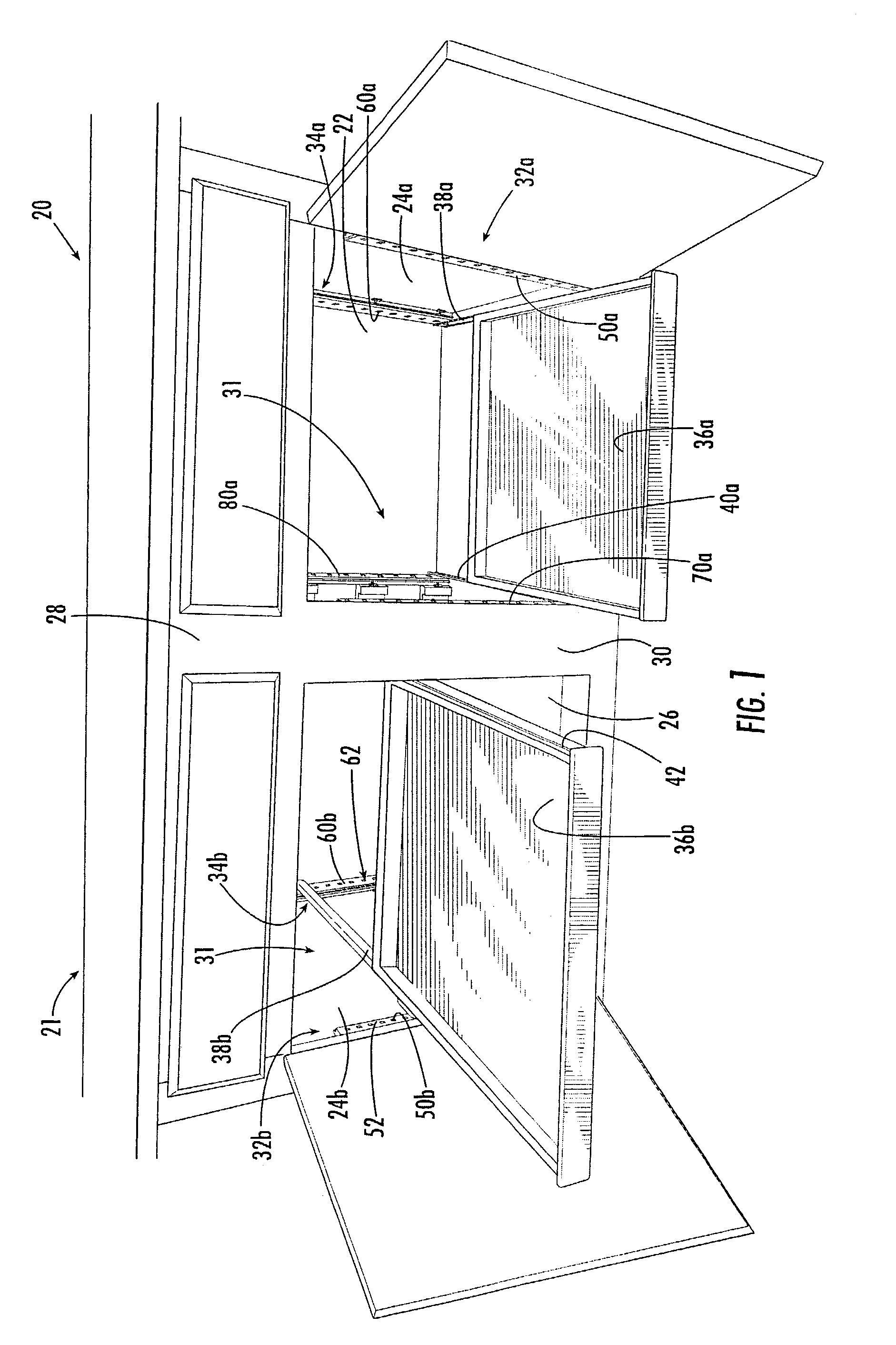
[0047]Referring now to the figures, a face-frame cabinet, designated broadly at 20, is illustrated in FIG. 1. The cabinet 20 includes an enclosure 21 having a rear wall 22, side walls 24a, 24b mounted perpendicular thereto, a floor 26 generally that is horizontally disposed, and a front wall 28 mounted generally parallel to the rear wall 22. The front wall 28 includes a vertical center member 30 that defines tw...


PUM


Abstract

A connector for supporting one or more mounting members that may be used in mounting a drawer within a cabinet includes: a vertically elongated base configured to abut an interior face of a wall of the cabinet and vertically elongated first and second mounting panels that are connected to and projecting outwardly from the base. The second mounting panel may be spaced apart from, and substantially parallel to, the first mounting panel, and the first and second mounting panels may extend from a base panel that extends perpendicular to the first and second mounting panels. The connector may also include an end panel that connects the distal end of the first mounting panel to the distal end of the second mounting panel.

Description

RELATED APPLICATION[0001]This application is a continuation-in-part application of co-assigned U.S. application Ser. No. 10 / 145,305 to Robert Hightower, filed May 13, 2002 now U.S. Pat. No. 6,840,590, the disclosure of which is hereby incorporated by reference herein in its entirety as if it were set forth fully herein.FIELD OF THE INVENTION[0002]The present invention is directed generally to furniture, and more particularly to cabinets with sliding drawers and trays.BACKGROUND OF THE INVENTION[0003]Many cabinets, particularly those found in kitchens, include drawers for storing various items. Often, drawers are mounted to the cabinet with elongate slide members that are fixed to the side walls of the drawer. Each slide member slidably engages a second elongate slide member that is fixed to the walls of the cabinet (often one of the slide members includes a small wheel that facilitates sliding motion). Some of such cabinets include multiple drawers, which can be disposed in vertical...

Claims


Application Information

Patent Timeline
Patent Type & Authority Patents(United States)
IPC IPC(8): A47B97/00A47B67/04A47B88/04
CPCA47B67/04A47B88/43
Inventor HIGHTOWER, ROBERT C.
Owner TENN TEX PLASTICS
Why Eureka
Try Eureka