Integrated magnetic device and direct current-direct current converter

a technology of integrated magnetic devices and converters, which is applied in the direction of electric variable regulation, process and machine control, instruments, etc., can solve the problems of low power output, high manufacturing cost, power loss, etc., and achieve the effect of reducing the size of dc-dc converters, reducing manufacturing costs, and improving the structure of im devices

Active Publication Date: 2022-03-08
MURATA MFG CO LTD
View PDF6 Cites 0 Cited by
  • Summary
  • Abstract
  • Description
  • Claims
  • Application Information

AI Technical Summary

Benefits of technology

[0009]Preferred embodiments of the present invention provide IM devices and DC-DC converters which each have a relatively small size and a low magnetic loss.
[0011]With a preferred embodiment of the present invention, a size of the IM device and a magnetic flux loss may be reduced, thus providing accurate voltage conversion. The magnetic core includes four magnetic columns. Windings are wound around the four magnetic columns to obtain multiple primary windings and multiple secondary windings, so that two IM devices are equivalently integrated. Further, according to the winding arrangement of the primary windings and the secondary windings on the magnetic core, reverse magnetic flux of two transformers after the integration are able to cancel each other, and thus a center column in an existing magnetic core is able to be canceled. This greatly reduces the size of the IM device. In addition, the cancellation of the center column may effectively reduce the magnetic flux loss and significantly improve conversion efficiency of the entire IM device.
[0013]With a preferred embodiment of the present invention, a size of the IM device and a magnetic flux loss may be reduced, thus providing accurate voltage conversion. The magnetic core includes four magnetic columns. Windings are wound around the four magnetic columns to obtain a primary winding and multiple secondary windings, so that two IM devices are equivalently integrated. Further, according to the winding arrangement of the primary winding and the secondary windings on the magnetic core, reverse magnetic flux of two transformers after the integration are able to cancel each other, and thus a center column in an existing magnetic core is able to be canceled. This greatly reduces the size of the IM device. In addition, the cancellation of the center column may effectively reduce the magnetic flux loss and significantly improve conversion efficiency of the entire IM device.
[0015]As a structure of the IM device is significantly improved, a size of the DC-DC converter is reduced accordingly, which enables the DC-DC converter to possess larger power with a smaller size and lower cost.

Problems solved by technology

The larger the size of the converter, the higher the manufacturing cost, and magnetic flux loss causes power loss.
Therefore, the existing techniques cannot provide a converter having a relatively small size and a high power output.

Method used


Image

  • Integrated magnetic device and direct current-direct current converter
  • Integrated magnetic device and direct current-direct current converter
  • Integrated magnetic device and direct current-direct current converter

Examples


Embodiment Construction

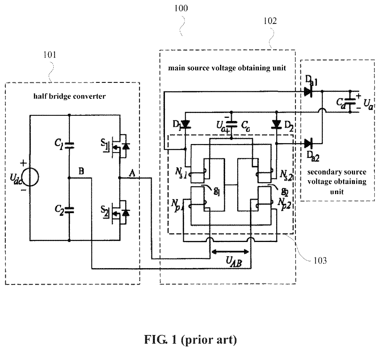
[0035]Preferred embodiments of the present invention provide IM devices and DC-DC converters. In following preferred embodiments of the present invention, IM devices are applied in a phase shift half bridge current doubler rectifier circuit. However, it is understood that the present invention is not limited thereto. The IM devices may be applied in other types of current doubler rectifier circuits.

[0036]Hereinafter, preferred embodiments of the present invention are described in detail with reference to drawings. Same portions are denoted by same reference numerals in the drawings. The preferred embodiments below are merely examples, and it is a matter of course that structures shown in different preferred embodiments may be partially replaced or combined. Common features among different preferred embodiments are omitted, and merely differences are described. In particular, same advantageous effects produced by same structures are not described one by one in each preferred embodime...


PUM

PropertyMeasurementUnit
output currentsaaaaaaaaaa
output voltagesaaaaaaaaaa

Abstract

An integrated magnetic device includes a magnetic core, primary windings and secondary windings, wherein the primary and secondary windings are wound around magnetic columns to define closed magnetic flux loop, the primary windings include a first primary winding wound around the first and second magnetic columns and a second primary winding wound around the third and fourth magnetic columns, winding directions of the first and second primary windings are opposite, when a voltage is applied to the primary windings, current flows through a portion of the secondary windings wound around the first magnetic column or a portion of the secondary windings wound around the second magnetic column due to induced electromotive force, and current flows through a portion of the secondary windings wound around the third magnetic column or a portion of the secondary windings wound around the fourth magnetic column due to induced electromotive force.

Description

CROSS REFERENCE TO RELATED APPLICATIONS[0001]This application claims the benefit of priority to Chinese Patent Application No. 201910009023.1 filed on Jan. 4, 2019 and Chinese Patent Application No. 201920013420.1 filed on Jan. 4, 2019. The entire contents of each application are hereby incorporated herein by reference.BACKGROUND OF THE INVENTION1. Field of the Invention[0002]The present invention generally relates to an integrated magnetic technology field, and more particularly, to an Integrated Magnetic (IM) device and a Direct Current-Direct Current (DC-DC) converter.2. Description of the Related Art[0003]For electric vehicle (EV) and hybrid electric vehicle (HEV) markets, Direct Current-Direct Current (DC-DC) converters able to convert high input voltages (about 200V to about 420V) to low output voltages (about 10.8V to about 14.2V) and high output currents (about 150 A) are quite essential devices.[0004]Currently, step-down converters have been widely used. For example, LLC co...

Claims


Application Information

Patent Timeline
Patent Type & Authority Patents(United States)
IPC IPC(8): H01F27/28H01F27/24H02M3/335H02M7/00H01F27/06
CPCH01F27/28H01F27/06H01F27/24H02M3/33569H02M7/003H01F27/38H01F27/40H01F2027/408H02M3/003H02M3/01H02M3/33573H02M3/33571H01F27/306
Inventor LI, GANG
Owner MURATA MFG CO LTD
Why Eureka
Try Eureka