
Keyswitch support connection structure and keyswitch structure therewith
a keyswitch and support technology, applied in the field of keyswitch structures, can solve the problems of increasing the degree of structural interference with the joining portion, and achieve the effects of increasing the structural interference of the joining portion, and increasing the structural interferen
- Summary
- Abstract
- Description
- Claims
- Application Information
AI Technical Summary
Benefits of technology
Problems solved by technology
Method used
Image

Examples
first embodiment
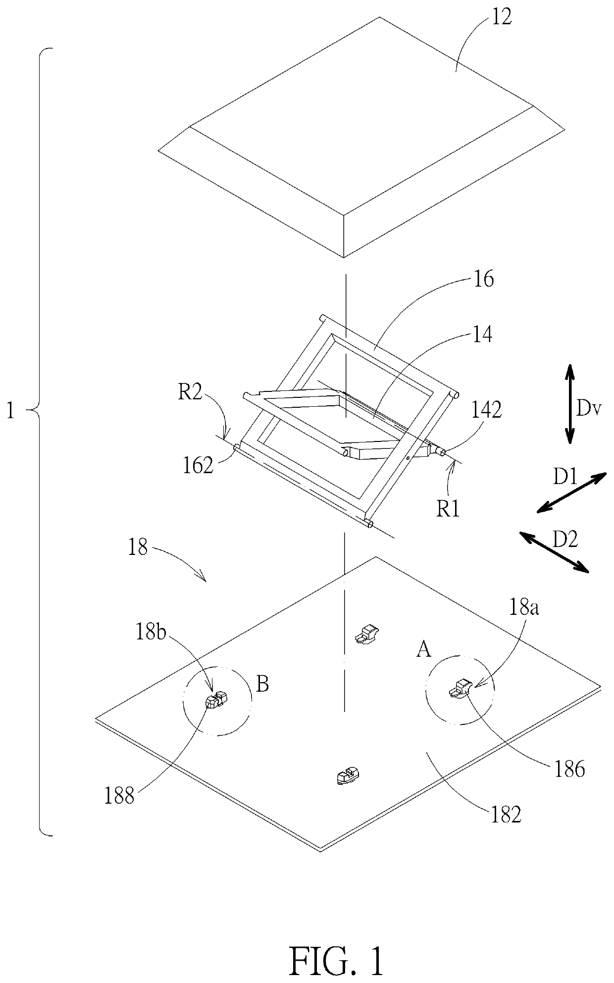
[0029]Please refer to FIG. 1. A keyswitch structure 1 includes a keycap 12, a first keyswitch support 14, a second keyswitch support16, and a base 18. The keycap 12 is disposed above the base 18. Both the first keyswitch support 14 and the second keyswitch support 16 are connected to and between the keycap 12 and the base 18, so that the keycap 12 can move vertically relative to the base 18 (or move parallel to a vertical direction Dv, indicated by a double-headed arrow in the figure) through the first keyswitch support 14 and the second keyswitch support 16. Therein, the base 18 includes two support connection portions 18a and two support connection portions 18b. The first keyswitch support 14 is rotatably and slidably connected to the base 18 through the support connection portion 18a. The second keyswitch support 16 is rotatably connected to the base 18 through the support connection portion 18b.
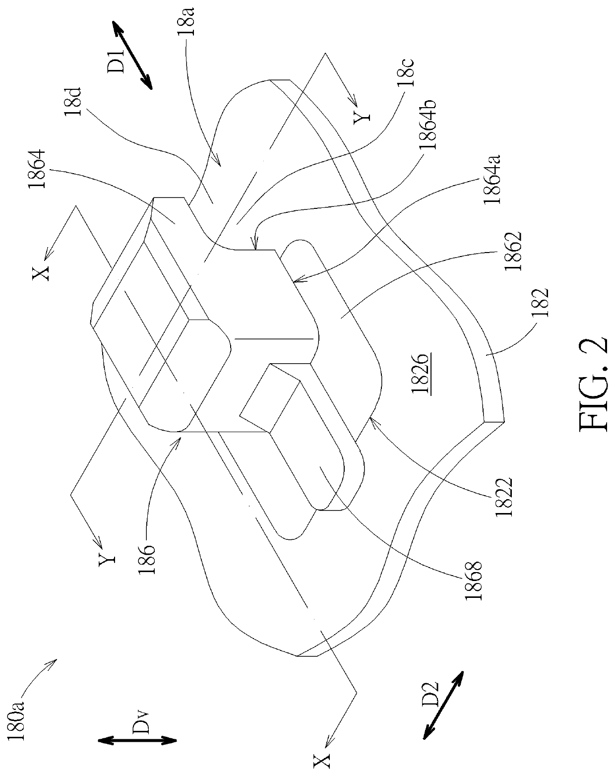
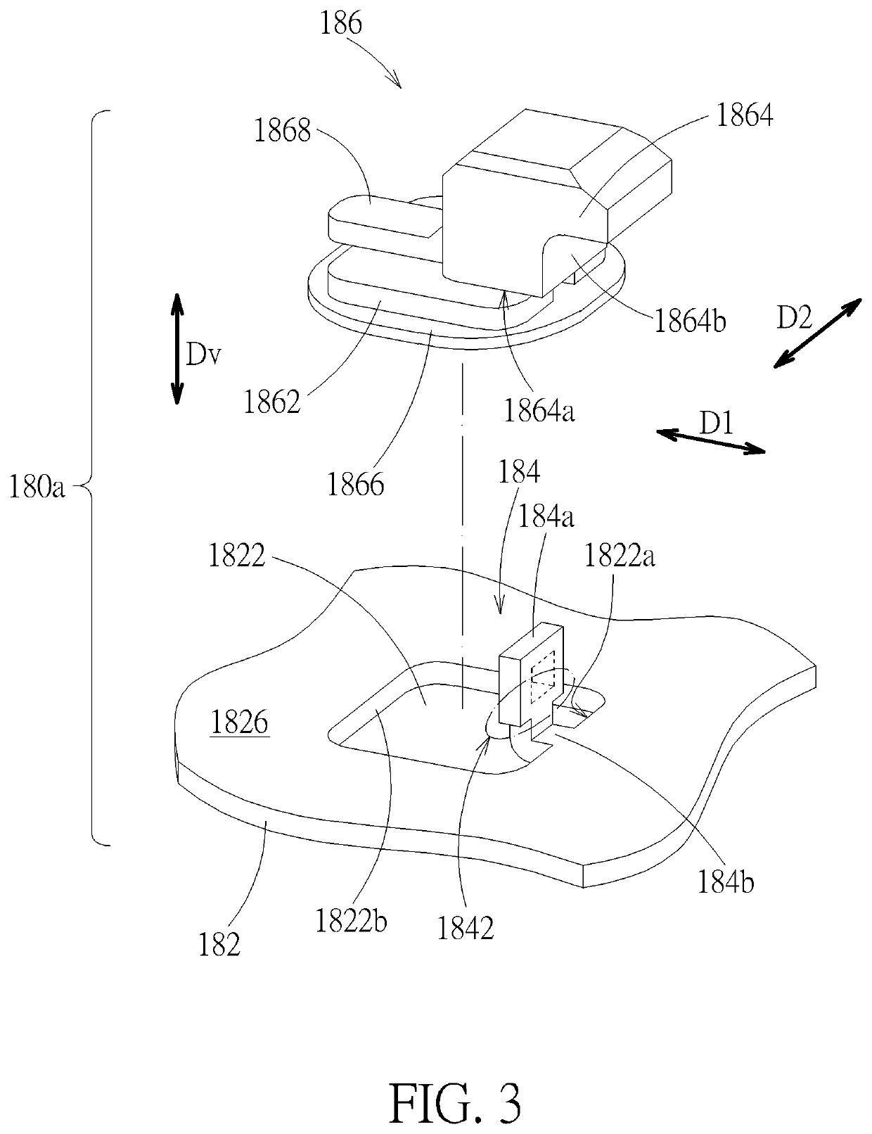
[0030]Please also refer FIG. 2 to FIG. 5. For the support connection portion 18a th...
eighth embodiment
[0050]Please refer to FIG. 18, which is a sectional view of an eighth embodiment, and of which the position of the cutting plan is equivalent to the line X-X in FIG. 2. FIG. 18 is roughly similar to the embodiment corresponding to FIG. 4. The difference relative to FIG. 4 is that the joining hole 1822 (referring FIG. 4) is further provided with a protruding bridge portion 1830a (i.e., the protruding bridge portion 1830 in FIG. 7 and FIG. 8). The protruding bridge portion 1830a is connected across two sides of the joining hole 182, which divides the joining hole 1822 into two portions from the view in the vertical direction Dv. That is, the protruding bridge portion 1830a divides the joining hole 1822 into exposed middle hole 1822b and side hole 1822c in the first direction D1. The middle hole 1822b and the side hole 1822c are connected by the space under the protruding bridge portion 1830a. The embedded portion 1862 fills up the middle hole 1822b, the side hole 1822c, and the connec...
PUM
 Abstract
Description
Claims
Application Information