Handheld type four-cycle engine

a four-cycle engine, hand-held technology, applied in machine/engine, valve drive, auxillary lubrication, etc., can solve the problems of engine main body, difficult to reduce weight, weight reduction,

Inactive Publication Date: 2001-10-18
HONDA MOTOR CO LTD
View PDF0 Cites 12 Cited by
  • Summary
  • Abstract
  • Description
  • Claims
  • Application Information

AI Technical Summary

Problems solved by technology

However, since the structure thereof is more complicated than that of two-cycle engines, there is a drawback that it is difficult to reduce the weight thereof.
Weight reduction is an important issue for improvements particularly in the operability of handheld four-cycle engines.
However, in the handheld type four-cycle engine disclosed in the abovementioned patent publication, a valve operation mechanism for ope

Method used


Image

  • Handheld type four-cycle engine
  • Handheld type four-cycle engine
  • Handheld type four-cycle engine

Examples


first embodiment

[0088] Firstly, the present invention shown in FIGS. 1 to 11 is explained below.

[0089] As shown in FIG. 1, a handheld type four-cycle engine E is attached as a source of power to the drive section of, for example, a powered trimmer T. Since the powered trimmer T is used in a manner in which a cutter C is positioned in various directions according to the operational conditions, the engine E is also tilted to a large extent or turned upside-down, as a result and the operational position is unstable.

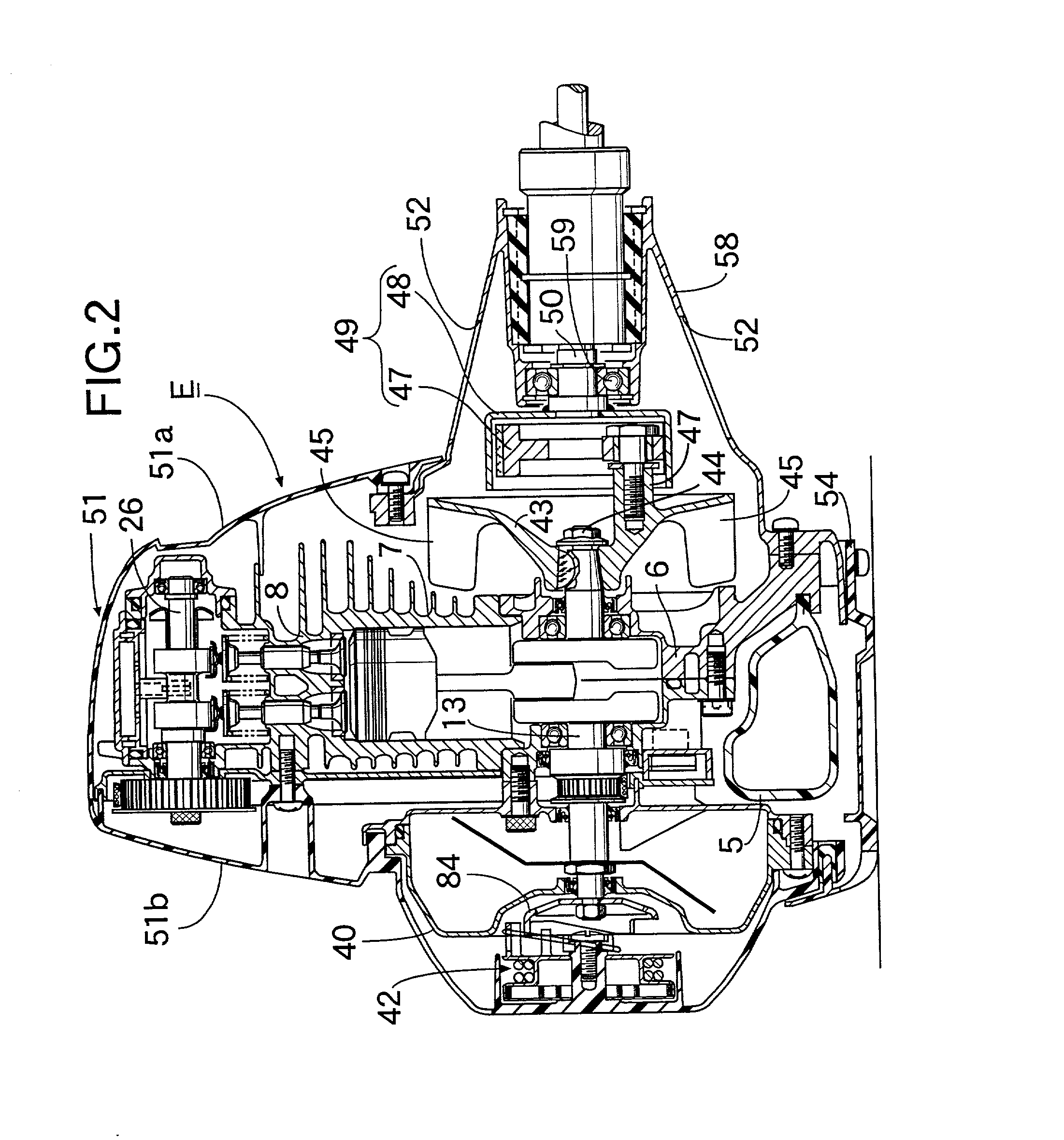
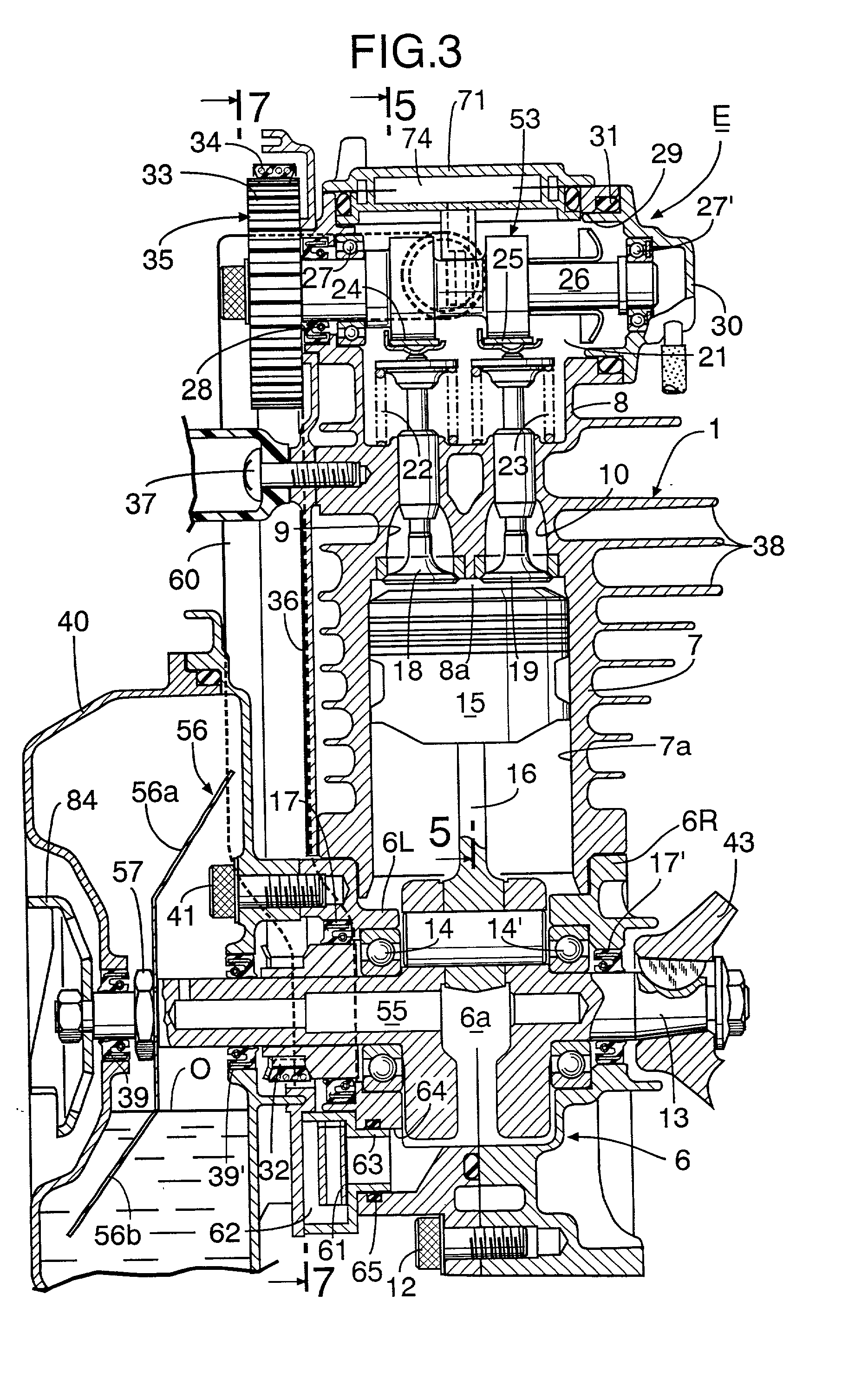
[0090] First of all, the overall construction of the handheld type four-cycle engine is explained by reference to FIGS. 2 to 5.

[0091] As shown in FIGS. 2, 3 and 5, a carburettor 2 and an exhaust muffler 3 are attached to the front and back respectively of an engine main body 1 of the above-mentioned handheld type four-cycle engine E, and an air cleaner 4 is attached to the inlet of the carburettor 2. A fuel tank 5 made of a synthetic resin is attached to the lower face of the engine main bo...

second embodiment

[0126] Next, the present invention is explained by reference to FIGS. 12 to 24.

[0127] As shown in FIGS. 12 and 13, a carburettor 102 and an exhaust muffler 103 are attached to the back and front respectively of an engine main body 101 of a handheld type four-cycle engine E, and an air cleaner 104 is attached to the inlet of the carburettor 102. A fuel tank 105 made of a synthetic resin is attached to the lower face of the engine main body 101. The two ends of a crankshaft 113 project out through the engine main body 101 and an oil tank 140 adjacent to one side of the engine main body 101, and a recoil type starter 142 which can be transmittably connected to a driven member 184 fixed to one end of the crankshaft 113 is mounted on the outer face of the oil tank 140.

[0128] A cooling fan 143 that also functions as a flywheel is fixed to the other end of the crankshaft 113. A plurality of fitting bosses 146 (one thereof is shown in FIG. 12) are formed on the outer face of the cooling fan...

third embodiment

[0186] Next, the present invention is explained by reference to FIGS. 25 to 36.

[0187] The external structure of the handheld type four-cycle engine E is explained by reference to FIGS. 25 and 26.

[0188] A carburettor 202 and an exhaust muffler 203 are attached to the front and back respectively of an engine main body 201 of the above-mentioned handheld type four-cycle engine E, and an air cleaner 204 is attached to the inlet of the carburettor 202. A fuel tank 205 made of a synthetic resin is attached to the lower face of the engine main body 201. The two ends of a crankshaft 213 project out of the engine main body 201 and an oil tank 240 adjacent to one side of the engine main body 201, and a recoil type starter 242 which can be transmittably connected to a driven member 284 fixed to one end of the crankshaft 213 is attached to the outer face of the oil tank 240.

[0189] A cooling fan 243 that also functions as a flywheel is fixed to the other end of the crankshaft 213. A plurality of...


PUM


Abstract

In a handheld type four-cycle engine, a valve operation mechanism includes a camshaft rotatably supported in a cylinder head so as to open and close an intake valve and an exhaust valve and a timing transmission placed on one side outside an engine main body and providing association between a crankshaft and the camshaft, and a centrifugal clutch for power output is mounted on the crankshaft on the opposite side outside the engine main body. The timing transmission and the centrifugal clutch being positioned at the two ends of the crankshaft improves the weight balance, the center of gravity of the engine can be made as close to the central part of the crankshaft as possible, which, together with the reduced weight, can enhance the operability of the engine.

Description

[0001] 1. Field of the Invention[0002] The present invention relates to handheld type four-cycle engines which are mainly used as a power source for machines for portable operation such as trimmers. More particularly, it relates to improvement of a four-cycle engine that includes an engine main body, the engine main body including a crankcase having a crank chamber, a cylinder block having a cylinder bore and a cylinder head having an intake port and an exhaust port; a crankshaft supported in the crankcase and housed inside the crank chamber; a piston fitted in the cylinder bore and connected to the crankshaft; an intake valve and an exhaust valve for opening and closing the intake port and exhaust port, the intake valve and exhaust valve being mounted in the cylinder head; a valve operation mechanism operable in association with the rotation of the crankshaft so as to open and close the intake valve and exhaust valve; and a power output or takeoff mechanism provided on one end of t...

Claims


Application Information

Patent Timeline
IPC IPC(8): F01L1/02F01M1/04F01M9/06F01M11/00F02B67/06F01M11/06F01M13/04F01P5/02F02B63/00F02B63/02F02B75/02F02B75/16F02F1/00F02F1/24
CPCF01L1/024F01M1/04F01M9/06F01M11/065F01M13/04F02B63/02F02B67/06F02B75/16F02B2075/027F02B2275/20F02F1/002F01L1/182
Inventor ITO, KEITAKASAI, KOJINISHIDA, TAKAOSHIMIZU, YASUHIROMAEDA, TAKESHIRYU, YASUTAKE
Owner HONDA MOTOR CO LTD
Why Eureka
Try Eureka