Universal clamp for a cylindrical element, in particular for a cable

a cylindrical element and universal clamp technology, applied in the direction of cables, cables for vehicles/pulleys, electrically conductive connections, etc., to achieve excellent contact pressur

Inactive Publication Date: 2002-12-19
NEXANS
View PDF1 Cites 1 Cited by
  • Summary
  • Abstract
  • Description
  • Claims
  • Application Information

AI Technical Summary

Benefits of technology

0012] These grooves provide excellent contact pressure against the cable and enable a force of at least 100 kilograms (kg) to be retained, without damaging the cable.

Problems solved by technology

Such clamps are made by machining since they would be too expensive to make by molding.

Method used


Image

  • Universal clamp for a cylindrical element, in particular for a cable
  • Universal clamp for a cylindrical element, in particular for a cable
  • Universal clamp for a cylindrical element, in particular for a cable

Examples


Embodiment Construction

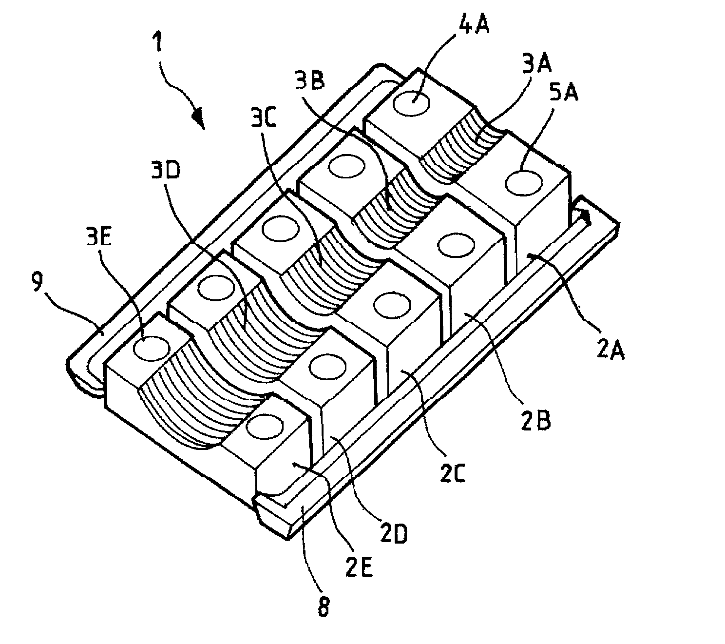
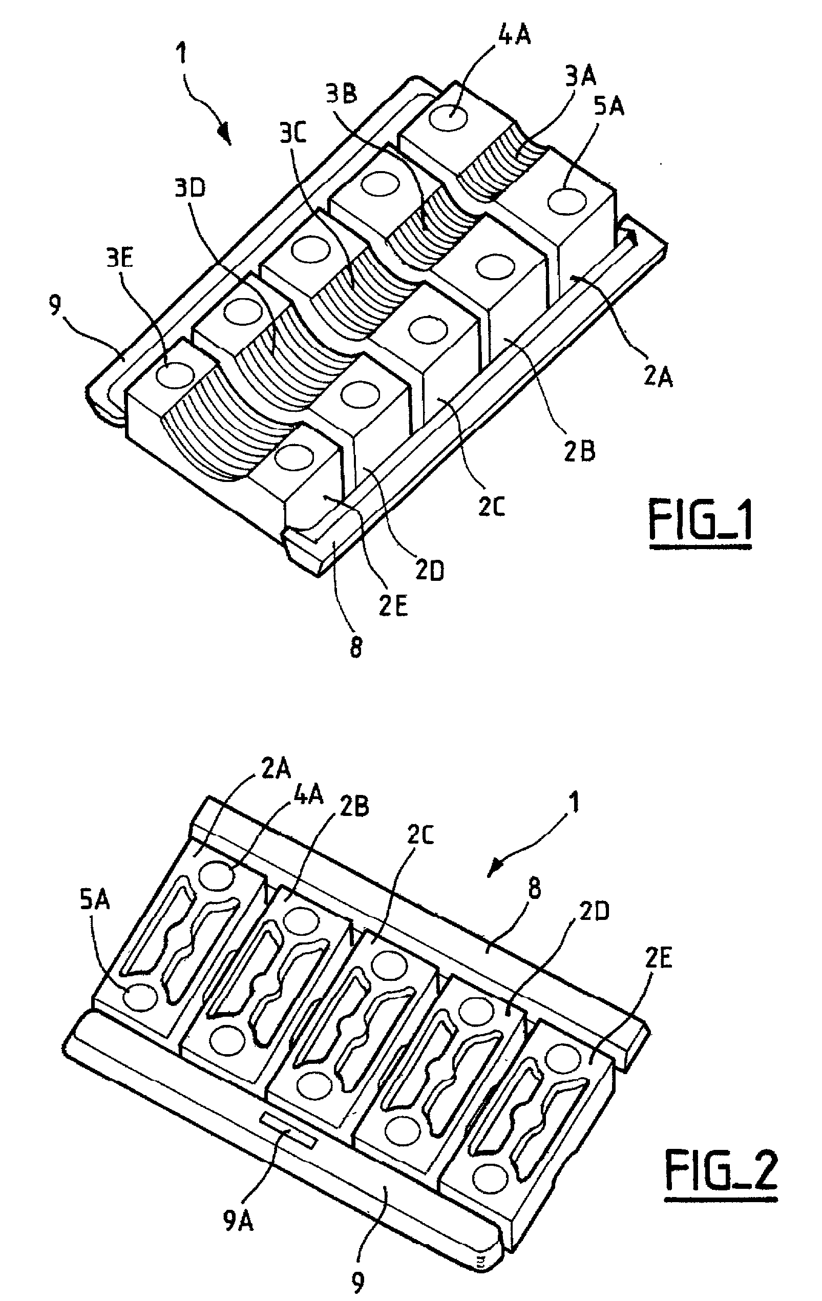
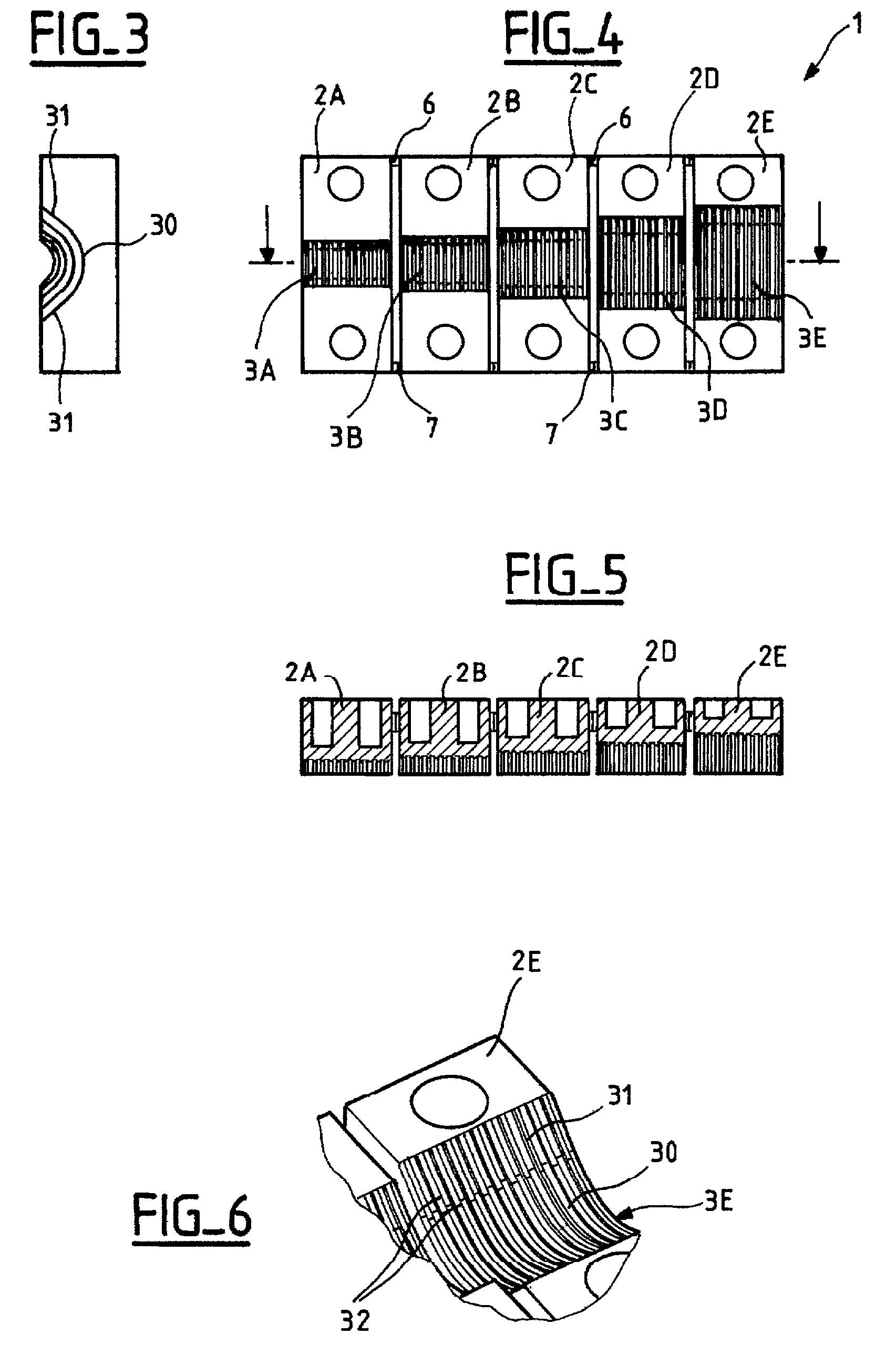
[0021] As can be seen in FIGS. 1 to 5, the invention provides a set of clamps 2A to 2E for fixing a cylindrical element, each clamp being constituted by a block provided in one of its faces with a respective channel 3A to 3E for receiving the cylindrical element, and also provided with clamping means.

[0022] The channels are centered in each block in conventional manner and the clamping means are constituted by two bores 4A and 5A each designed to receive a bolt and disposed on either side of the corresponding channel 3A.

[0023] The assembly 1 comprises a plurality of clamps 2A to 2E having channels of different dimensions and interconnected by at least breakable element. The breakable element can be broken manually or using a tool such as a screwdriver. In conventional manner, it is advantageously constituted by fine connection tongues 6 and 7.

[0024] The clamps are disposed in alignment side by side so as to form a strip of clamps, with the size of the channel increasing from the fir...


PUM


Abstract

The present invention relates to a set of fixing clamps for fixing a cylindrical element, each clamp being constituted by a block provided on one of its faces with a channel for receiving the cylindrical element, and also provided with clamping means. The set comprises a plurality of clamps having respective channels of different dimensions and connected to one another via at least one breakable element.

Description

[0001] The present invention relates to a universal clamp for a cylindrical element, in particular for a cable.[0002] More precisely, the invention relates to a set of fixing clamps for cylindrical elements, each clamp comprising a block provided with a channel in one of its faces for receiving a cylindrical element, and with clamping means.[0003] Such known clamps are constituted by a block of machined metal and they are generally used in pairs. The cylindrical element, in particular a power cable or an optical fiber cable is held between two clamps and is received in the corresponding cylindrical channels. At present, these clamps are made individually with determined channel diameters.[0004] Such clamps are made by machining since they would be too expensive to make by molding. Each cable diameter corresponds to a particular size of clamp, and thus to a particular part to be managed, specifically in terms of storage and assembly.OBJECTS AND SUMMARY OF THE INVENTION[0005] The inve...

Claims


Application Information

Patent Timeline
Patent Type & Authority Applications(United States)
IPC IPC(8): F16G11/06G02B6/44H01R4/64H02G3/32H02G15/013
CPCF16G11/06G02B6/4477H02G15/013H02G3/32H01R4/646
Inventor VINCENT, ALAINAPERE, RODOLPHE
Owner NEXANS
Why Eureka
Try Eureka