Female contact

A contact part and female mold technology, which is applied in the direction of contact parts, parts of connecting devices, connections, etc., can solve problems such as reliability decline

Pending Publication Date: 2019-04-19
TYCO ELECTRONICS JAPAN GK
View PDF11 Cites 0 Cited by
  • Summary
  • Abstract
  • Description
  • Claims
  • Application Information

AI Technical Summary

Problems solved by technology

If the distance between the two contact spring parts exceeds the elastic limit, the contact pressure with the male die contact will not be obtained, resulting in a decrease in the reliability of conduction.

Method used


Image

  • Female contact
  • Female contact
  • Female contact

Examples


Embodiment Construction

[0032] Embodiments of the present invention will be described below.

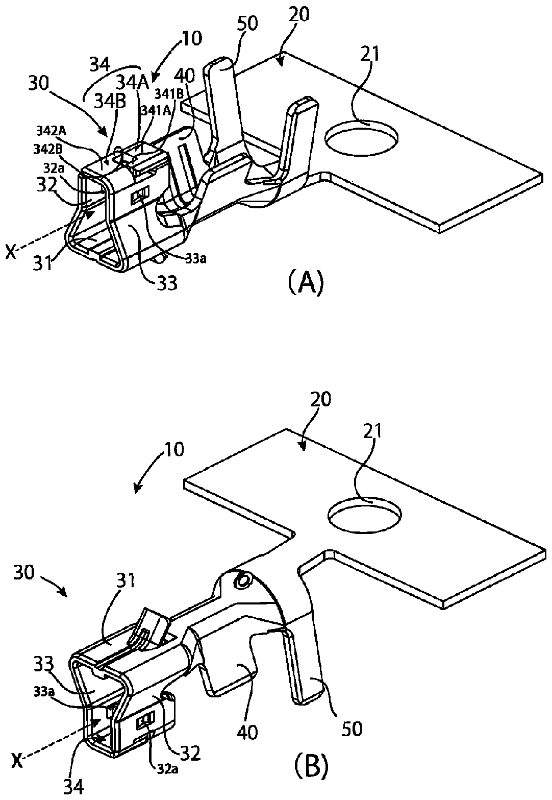
[0033] figure 1 It is a perspective view of the die contact which is one embodiment of this invention. here, figure 1 (A) and (B) are perspective views showing the same female die contact upside down.

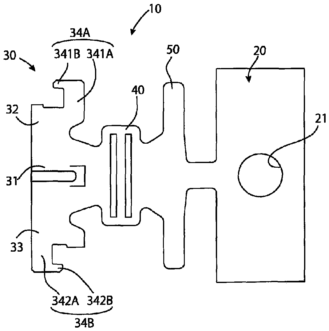
[0034] in addition, figure 2 is in figure 1 A three-sided view of the female contact in perspective view is shown in . here, figure 2 (A), (B) and (C) are top view, front view and side view, respectively.

[0035] In these figure 1 , figure 2 The female mold contact 10 shown is crimped connected with wires (not shown), and in figure 1 , figure 2 In , the female contact is shown in the shape before wire crimping.

[0036] And, in figure 1 , figure 2 The female contact 10 is shown with a bracket 20 attached thereto. figure 1 , figure 2 The bracket 20 is shown as a portion corresponding to one female contact, and actually, the bracket 20 has a long-dimensioned strip shape. Furthermore, in ...


PUM


Abstract

The present invention provides a female contact whose cost is reduced while securing a good contact pressure with a male contact. A female contact 10 has a ceiling portion 34 composed of a first ridgeportion 34A and a second ridge portion 34B. The first collar portion 34A has a first arm portion 341A extending from the upper end edge of the first contact spring portion 32 toward the second contact spring portion 33. In addition, the second flange portion 34B has a second arm portion 341B extending from the upper end edge of the second contact spring portion 33 toward the first contact springportion 32 side. Furthermore, the first hook portion 34A has a first claw portion 342A extending toward the second arm portion 341B. In addition, the second hook portion 34B has a second claw portion342B extending away from the first claw portion 342A toward the first arm portion 341A. When the distance between the first contact spring portion 32 and the second contact spring portion 33 expands to a predetermined distance, the first claw portion 342A and the second claw portion 342B engage with each other to prevent the expansion beyond the same.

Description

technical field [0001] The present invention relates to a female die contact. The female die contact has a base and two contact springs. The two contact springs stand up from the two side edges of the base and sandwich an inserted rod-shaped male contact. Die contacts. Background technique [0002] There are cases where a force that greatly expands the distance between the two contact spring portions acts on the female contact with the above-described structure. For example, when the male contact is inserted obliquely with respect to the standard insertion direction, such a force acts. If the distance between the two contact spring parts exceeds the limit of elasticity, the contact pressure with the male contact will not be obtained, leading to a reduction in the reliability of conduction. [0003] Here, Patent Document 1 discloses a connection terminal having a structure in which two side plates corresponding to the above-mentioned two contact spring portions are locked w...

Claims


Application Information

Patent Timeline
Patent Type & Authority Applications(China)
IPC IPC(8): H01R13/11
CPCH01R13/11H01R13/428
Inventor 坂井健
Owner TYCO ELECTRONICS JAPAN GK
Why Eureka
Try Eureka