Design method of non-circular C-shaped damping ring with controllable contact pressure

A technology of contact pressure and design method, applied in mechanical equipment, sustainable transportation, geometric CAD, etc., can solve the problems of material deformation, increase friction energy consumption, uncontrollable contact pressure, etc., achieve high contact rate, avoid vibration damping performance The effect of reducing and uniform contact pressure

Active Publication Date: 2022-05-27
CHONGQING UNIV
View PDF2 Cites 0 Cited by
  • Summary
  • Abstract
  • Description
  • Claims
  • Application Information

AI Technical Summary

Problems solved by technology

However, the working contact pressure of this kind of damping ring is highly dependent on the centrifugal field formed by the high speed, and the contact pressure is uncontrollable, which increases the difficulty of designing the optimal contact pressure required to achieve the maximum frictional energy consumption
[0005] (2) Since the diameter of the ring groove is slightly smaller than the maximum size of the damping ring, the damping ring can be installed into the ring groove to form a preload. Therefore, although the perfect circular C-shaped damping ring is round in the natural state, the material after being installed into the ring groove Deformation, the damping ring can only be in partial contact with the gear, that is, a non-contact area is formed, which not only leads to uneven distribution of contact pressure, but also loses the effective area where the damping ring participates in frictional energy consumption, thereby reducing the damping ring's vibration reduction capability
Although, as the speed increases, the non-contact area is gradually shrinking, but this shrinking rate is slowing down, and even if the speed increases to a higher level, the non-contact area has not completely disappeared
[0006] (3) The existing C-shaped damping ring is designed according to empirical formulas and data, but this kind of damping ring has disadvantages such as uncontrollable contact pressure and obvious non-contact area, and there is still no effective improvement design method at present

Method used


Image

  • Design method of non-circular C-shaped damping ring with controllable contact pressure
  • Design method of non-circular C-shaped damping ring with controllable contact pressure
  • Design method of non-circular C-shaped damping ring with controllable contact pressure

Examples


Embodiment 1

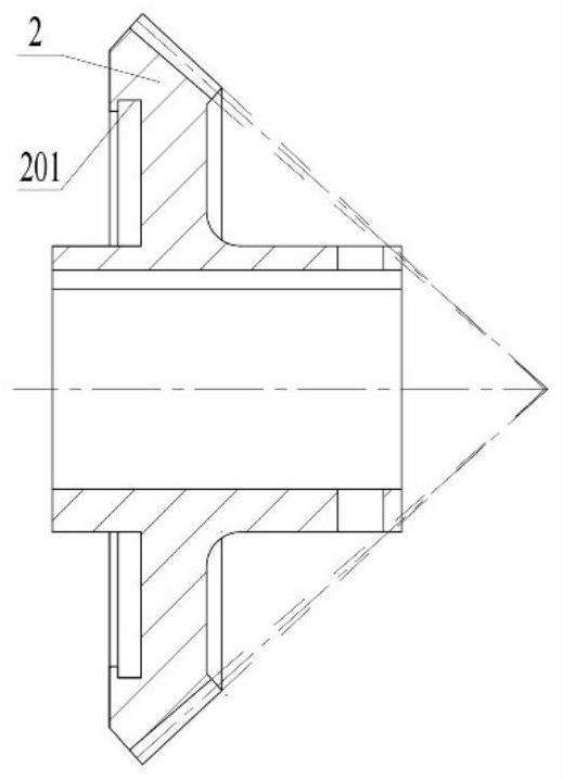
[0138] Designed to be attached to an aviation high-speed thin-spoke bevel gear (such as figure 2 The non-circular C-shaped damping ring shown in ) is designed according to the specific process of the present invention to realize the design method of the non-circular C-shaped damping ring with controllable contact pressure, and the steps are as follows:

[0139] (1) Given the design parameters and target gear parameters, and determine the non-circular C-shaped damping ring section parameters. Given the harmful resonance point frequency f=2895Hz of the target gear, and specify the design contact pressure p d =0.8MPa. Given the number of teeth of the target gear z=86, the radius of the ring groove r g =50.5mm, ring groove width w g =4.0mm, ring groove depth t d =2.0mm. According to the cross-sectional parameter requirements of the non-circular C-shaped damping ring (the range of the axial width w is (0,0.99w g ], the range of radial thickness t is t≥t d ), and the axial w...

Embodiment 2

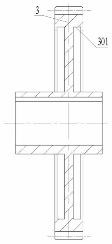
[0148] Designed to be attached to an aviation high-speed thin-spoke spur gear (such as image 3 The non-circular C-shaped damping ring shown in Figure 1 is designed according to the specific process of the present invention to realize the design method of the non-circular C-shaped damping ring with controllable contact pressure, and the steps are as follows:

[0149] (1) Given the design parameters and target gear parameters, and determine the non-circular C-shaped damping ring section parameters. Given the harmful resonance point frequency f=5744Hz of the target gear, and specify the design contact pressure p d =0.7MPa. Given the number of teeth of the target gear z=96, the radius of the ring groove r g =65.0mm, ring groove width w g =4.9mm, ring groove depth t d =2.0mm. According to the cross-sectional parameter requirements of the non-circular C-shaped damping ring (the range of the axial width w is (0,0.99w g ], the range of radial thickness t is t≥t d ), and the ax...


PUM


Abstract

The invention provides a design method of a non-circular C-shaped damping ring with controllable contact pressure. Based on the design method, corresponding non-circular C-shaped damping ring free profiles can be designed according to different contact pressure requirements, so that the contact pressure depends on the gear rotating speed and also depends on profile deformation, and the problem that the contact pressure is uncontrollable under the designed rotating speed is solved; and the optimal contact pressure corresponding to the maximum vibration reduction efficiency of the damping ring can be obtained under the designed rotating speed. Based on the design method, the contact pressure between the damping ring and the gear is uniformly distributed, and the contact rate is high. When the vibration damper is installed in a gear, even contact pressure can be generated, the contact rate is high, and the situation that the vibration damping performance is reduced due to a non-contact area can be avoided.

Description

technical field [0001] The present invention relates to a design method of a damping member. Background technique [0002] When the aviation high-speed thin-spoke gear accumulates excessive vibration energy due to traveling wave resonance, sudden traveling wave resonance damage is very likely to occur. The property is pitch-diameter fatigue fracture. The broken tooth block directly threatens the safety of the entire transmission system and even the engine. This form of failure and damage has caused many major flight failures. Therefore, the risk of traveling wave resonance damage of aviation high-speed thin-spoke gears is extremely high, and effective measures should be taken to reduce the vibration energy during traveling wave resonance to avoid the risk of failure. technical means. [0003] The C-shaped damping ring can be used to reduce the vibration energy during traveling wave resonance and weaken the influence of resonance on the gear transmission system. However, ...

Claims


Application Information

Patent Timeline
Patent Type & Authority Applications(China)
IPC IPC(8): G06F30/15G06F17/13F16H55/14
CPCG06F30/17G06F30/15G06F17/13F16H55/14G06F2119/14Y02T90/00
Inventor 魏静徐子扬刘指柔魏海波陈向前
Owner CHONGQING UNIV
Why Eureka
Try Eureka