Anti-noise starter flywheel

a starter flywheel and anti-noise technology, applied in the direction of mechanical control devices, lifting devices, controlling members, etc., can solve the problem of significantly reducing the noise power generated, and achieve the effect of reducing the volume of the sound

Inactive Publication Date: 2003-07-24
DEFONTAINE
View PDF12 Cites 1 Cited by
  • Summary
  • Abstract
  • Description
  • Claims
  • Application Information

AI Technical Summary

Benefits of technology

0013] By putting a viscoelastic material element situated between the radial surface of the support and the complementary radial surface of the ring under stress in at least all of the directions of a right section of said element, the sound volume is reduced significantly: the noise power at a frequency situated above the resonant frequency of the flywheel (2000 Hz) is reduced by about 9 decibels (dB). In addition, some of the noise at a frequency lower than the resonant frequency of the flywheel is lowered in frequency.

Problems solved by technology

The problem posed is to reduce significantly the noise power generated when starting internal combustion engines.

Method used


Image

  • Anti-noise starter flywheel
  • Anti-noise starter flywheel

Examples


first embodiment

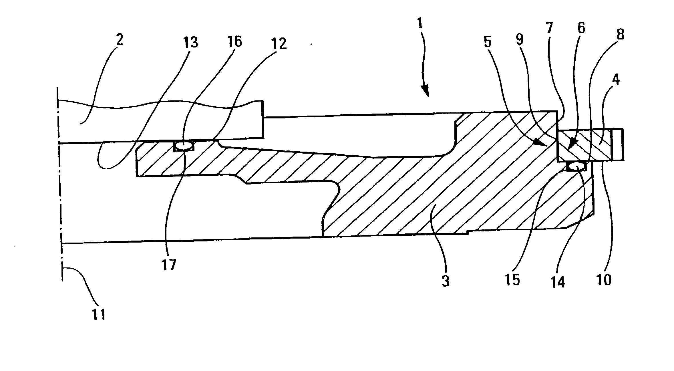
[0020] In the first embodiment shown in FIG. 1, the ring gear 4 is connected to the support 3 by fixing the complementary peripheral surface 9 to the peripheral surface 7. This fixing can be as an interference fit or by welding. It may be implemented by any of the means described in European patent application No. EP 00 / 402 629.0.

second embodiment

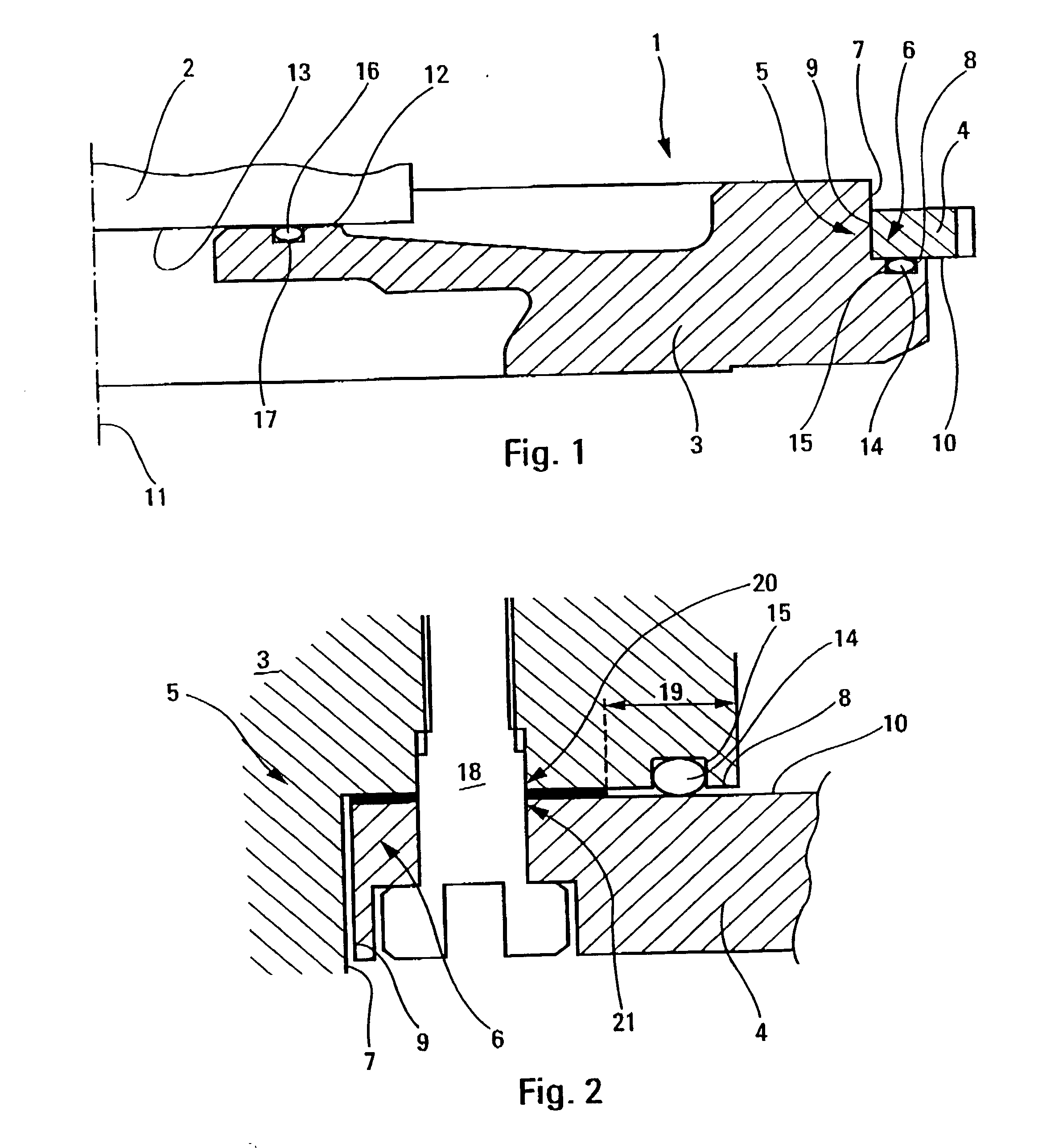
[0021] In the second embodiment shown in FIG. 2, the ring gear 4 is connected to the support 3 by fixing the complementary radial surface 10 to the radial surface 8 by means of screws 18: the peripheral surface 7 and the complementary peripheral surface 9 are spaced apart by clearance preventing these two surfaces coming into contact with each other and making it possible in particular to place the ring gear 4 around the surface 7.

[0022] Closer to the axis of rotation 11, the support 3 has a radial bearing surface 12 via which it is fixed to a radial reception surface 13 on the crankshaft 2.

[0023] In the present invention, an element 14 of viscoelastic material is placed between the radial surface 8 of the support 3 and the complementary radial surface 10 of the ring gear 4.

[0024] This element 14 of viscoelastic material is put under stress in all directions.

[0025] In the example shown in FIGS. 1 and 2, the element 14 of viscoelastic material is an annular gasket 14. The gasket 14 i...


PUM


Abstract

The flywheel of all internal combustion engine comprises a support and a ring gear. The outer peripheral end of the support has a radial surface and the inner peripheral end of the ring gear has a complementary radial surface. An element of viscoelastic material is situated between the radial surface and the complementary radial surface in such a manner as to put under compression stress in the radial and axial directions.

Description

[0001] The present invention relates to a flywheel suitable for meshing with a pinion of a starter used for starting an internal combustion engine, in particular for vehicles such as automobiles.[0002] Flywheels are known of the type that comprises a support adapted to be mounted axially on the outlet shaft of the engine and a ring gear which possesses an inner peripheral end whereby it is fixed to the outer peripheral end of the support.[0003] A large amount of noise is generated when starting an internal combustion engine. This noise is unpleasant not only for the driver and passengers of the vehicle, but also for passersby. Starting on multiple occasions makes this more unpleasant. This unpleasant sound tarnishes the image of the vehicle.[0004] Starting noise is generated by the starter pinion penetrating into the ring gear of the flywheel, and then by those two parts meshing.[0005] One of the causes of the high level of noise is the small gear ratio between the number of teeth o...

Claims


Application Information

Patent Timeline
Patent Type & Authority Applications(United States)
IPC IPC(8): F02B77/00F02N11/00F02N15/02F02N15/06F16F15/131F16F15/30F16H55/14
CPCF02N15/02F02N15/063Y10T74/2131F16H55/14F16F15/13164
Inventor BONNEFOUS, JEANDOUILLARD, FRANKGAUDU, SERGE
Owner DEFONTAINE
Why Eureka
Try Eureka