Electronically controlled prosthetic system

a prosthetic foot and electric motor technology, applied in the field of electric motor controlled prosthetic feet, can solve the problems of insufficient prior art on numerous levels, current mechanically designed prosthetic feet do not allow significant alterations in gait speed without losing optimal biomechanical characteristics

Inactive Publication Date: 2004-03-18
MARTIN JAMES JAY
View PDF8 Cites 202 Cited by
  • Summary
  • Abstract
  • Description
  • Claims
  • Application Information

AI Technical Summary

Problems solved by technology

Although, it is known in the art to manufacture ankle and foot prosthetic combinations that have generally increased performance and appearance, the prior art is still deficient on numerous levels as will be discussed in greater detail below.
Typically, models aligned for such activities as daily walking are not optimally aligned for running and vise versa.
Furthermore, while prior art prosthetic devices may have generally moved amputees toward more biomechanically appropriate gait patterns, current mechanically designed prosthetic feet do not allow for significant alterations in gait speed without losing optimal biomechanical characteristics essential with walking or running.
Unfortunately, neither provides both optimal energy return and uneven ground accommodation sufficiently to meet user needs.
Another consideration lacking in the prior art of ankle and foot devices is the combination of aesthetics and function.
A common complaint of many prosthetic foot users is that their prosthetic foot "sticks up" when they sit.
This remains a problem due...

Method used


Image

  • Electronically controlled prosthetic system
  • Electronically controlled prosthetic system
  • Electronically controlled prosthetic system

Examples


Embodiment Construction

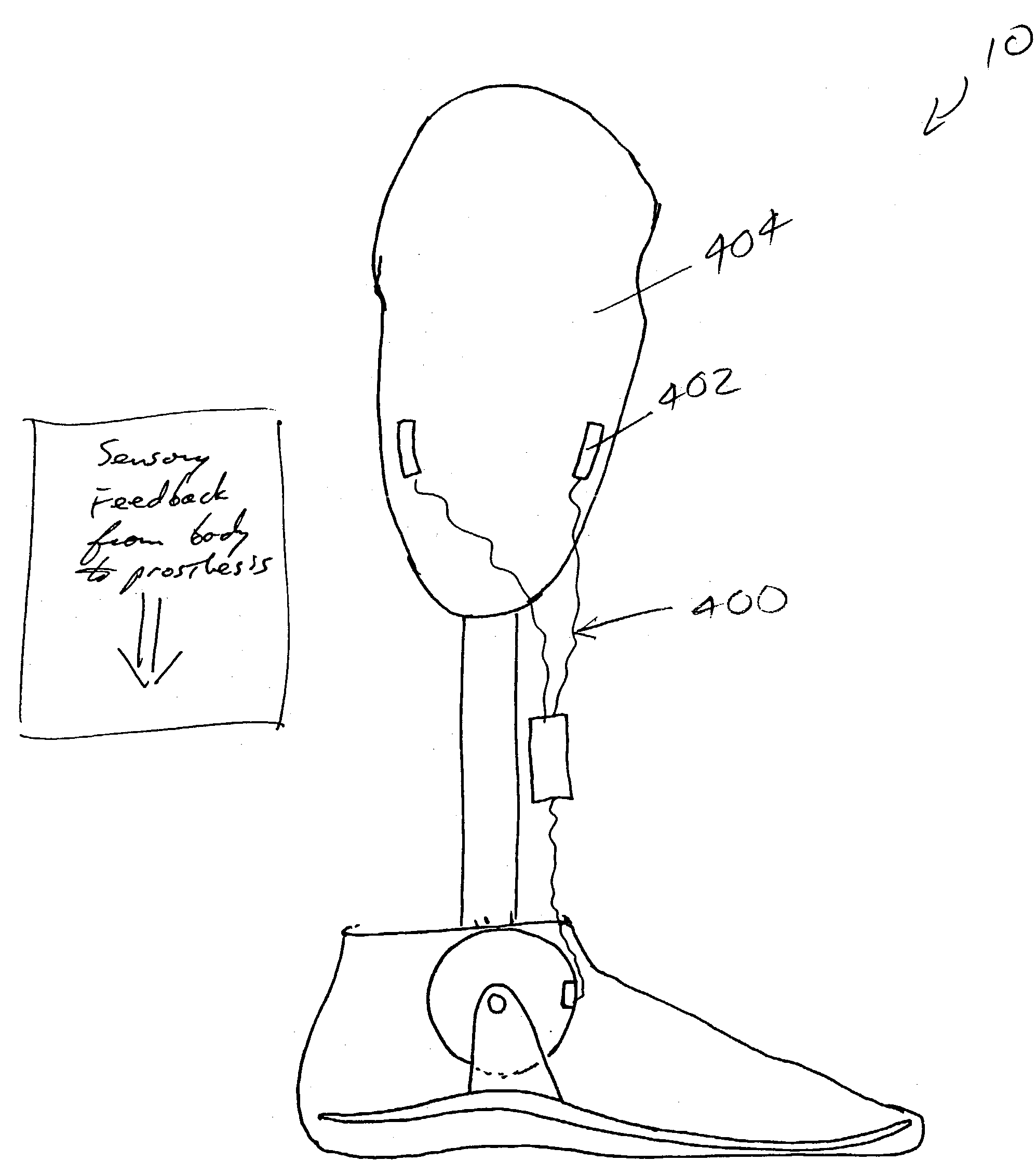
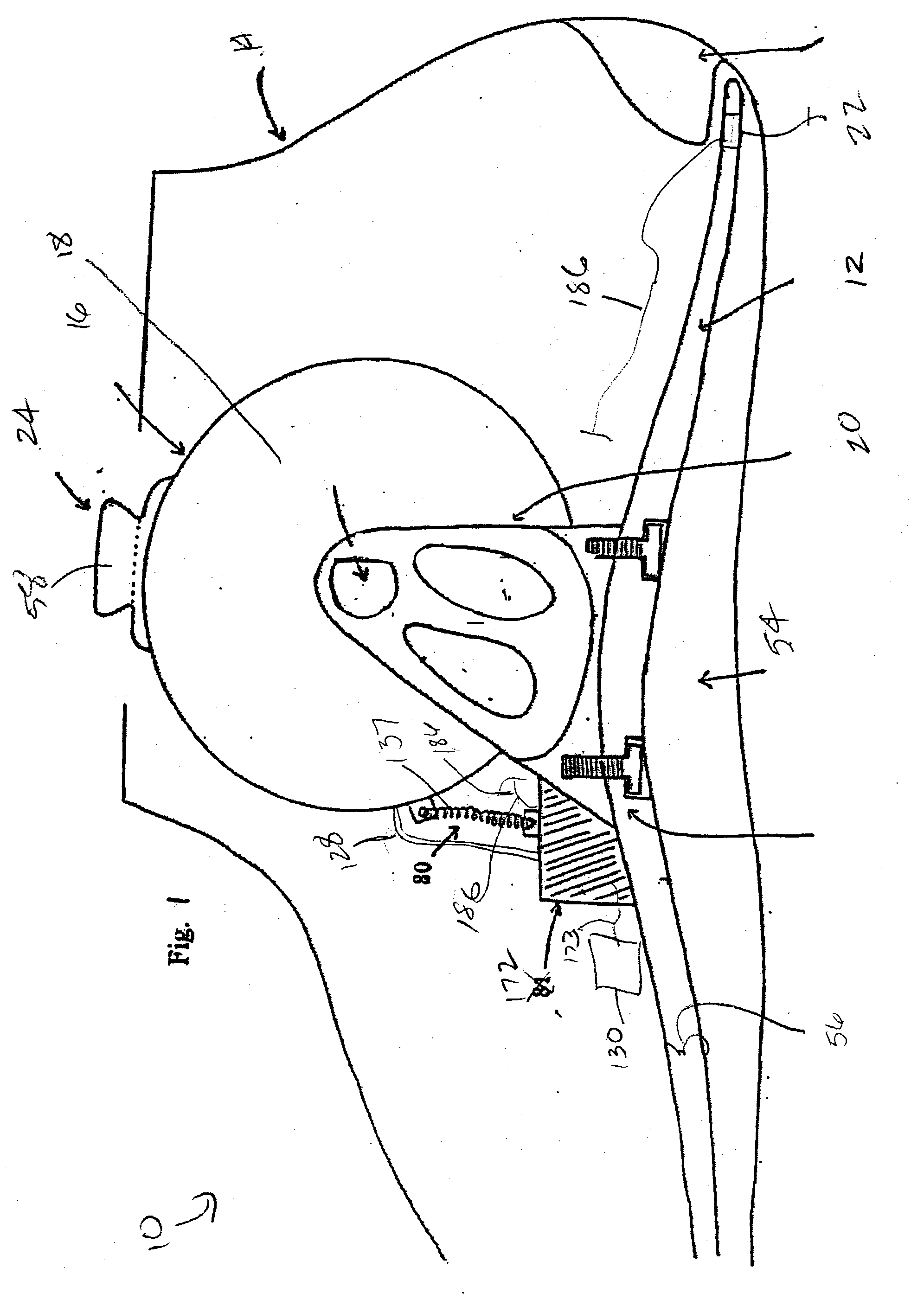
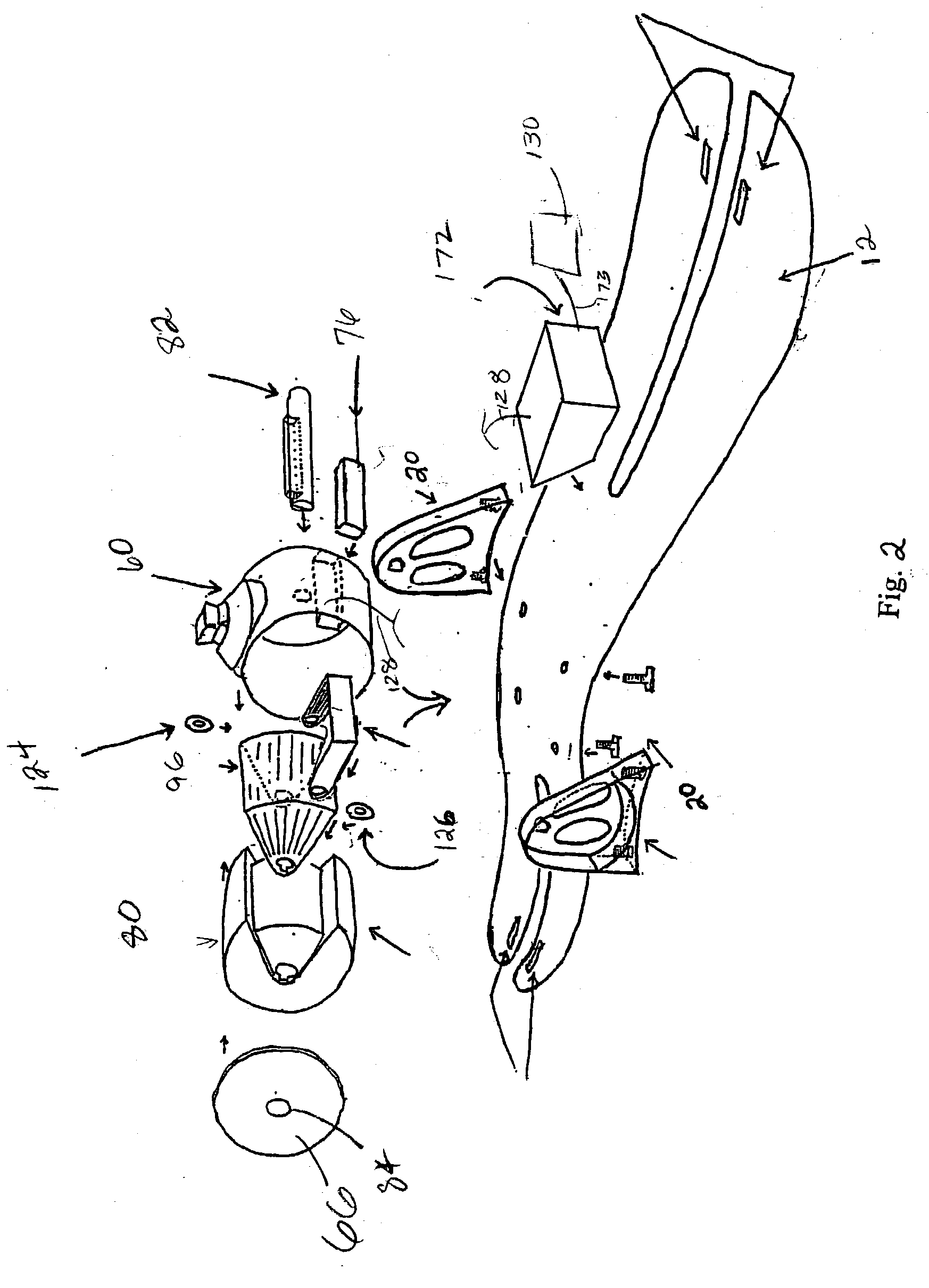
[0189] Additionally, it is contemplated that invention 10 may be used in conjunction with myoelectric muscle contacts on the residual limb 404 for trans-tibial amputees and may provide greater control in ambulation. By example, at heel strike, tibialis anterior contraction may be used to determine the level of damper resistance of MR fluid 94 preventing or reducing too fast or too much plantarflexion. Also, increased gastrocnemeous contraction during midstance may initiate dorsiflexion resistance sooner to allow keel 12 to remain in increased plantarflexion from midstance to toe off, therefore increasing push off may be utilized in fast walking or running.

[0190] Furthermore, invention 10 maybe used in conjunction with an orthotic device for a user who has lost the ability to actively plantarflex and / or dorsiflex their natural foot. It is contemplated that invention 10 dampening system 18, sensor system 22, microprocessor unit 172 and / or other elements or combinations thereof device ...


PUM


Abstract

A prosthetic joint system for users comprising a housing having an interior cavity, a center axis in said interior cavity, and an attachment means for fixedly connecting said housing to said user; an inner cylinder disposed in said housing interior cavity wherein said inner cylinder rotates around said center axis of said housing; an appendage attached to said inner cylinder; a sensor system attached to said appendage; and a dampening system, having a power source, in communication with said sensor system, said inner cylinder, and said housing for controlling dampening of the rotation of said inner cylinder around said center axis of said housing.

Description

[0001] Priority is claimed from provisional patent application U.S. Ser. No. 60 / 371,974, filed on Apr. 12, 2002, and incorporated by reference herein.[0002] The present invention relates generally to an ankle and foot joint system. More particularly, the present invention is a new and improved prosthetic joint system which simulates natural human locomotion and human biomechanics through sensory feed back, time feedback, electronically controlled dampening joint assembly, and a microprocessor control system.DESCRIPTION OF THE KNOWN PRIOR ART[0003] As the study of human physiology and anatomy clearly demonstrates, the relative simple action of walking on an even flat surface involves numerous biomechanical complexities. A single step requires constant biofeedback such as continual analysis of proprioception, angulations, timing, and balanced muscular-skeletal functions. In the prior art, the prosthetic industry is continuously attempting to mimic natural human locomotion (NHL), perfo...

Claims


Application Information

Patent Timeline
IPC IPC(8): A61F2/00A61F2/50A61F2/58A61F2/60A61F2/64A61F2/66A61F2/68A61F2/70A61F2/72A61F2/76
CPCA61F2/581A61F2250/008A61F2/585A61F2/605A61F2/64A61F2/6607A61F2/68A61F2/72A61F2002/5001A61F2002/5003A61F2002/5004A61F2002/5018A61F2002/5021A61F2002/503A61F2002/5032A61F2002/5033A61F2002/5041A61F2002/5043A61F2002/6621A61F2002/6642A61F2002/6685A61F2002/6818A61F2002/6854A61F2002/6863A61F2002/701A61F2002/704A61F2002/705A61F2002/7635A61F2002/7655A61F2/582A61F2/70
Inventor MARTIN, JAMES JAY
Owner MARTIN JAMES JAY
Why Eureka
Try Eureka