Organic electroluminescence display device

a display device and electroluminescence technology, applied in the field of organic electroluminescence display devices, can solve the problems of reduced reflected external light, reduced light emitted by the device, so as to achieve enhanced contrast of display devices, low cost, and enhanced contrast ratio

Inactive Publication Date: 2004-09-30
RITDISPLAY
View PDF4 Cites 29 Cited by
  • Summary
  • Abstract
  • Description
  • Claims
  • Application Information

AI Technical Summary

Benefits of technology

0013] One of the conventional technologies provides a polarizer attached to the surface of the display device, or provides a photo sensor and an adjusting device of contrast ratio to solve the problem described above. However, these two methods have the disadvantages below. First, the reflected external light is reduced by the polarizer, however, the light emitted by the device is also reduced by the polarizer, therefore the contrast of the display device is not enhanced and is not applicable for the display device to be used outdoors. Next, the photo sensor and the adjusting device of the contrast ratio are dependent on the intensity of the external light, thus the cost is high.
0014] Therefore, the present invention is directed to an organic electroluminescence display device having a selective light valve. The selective light valve is used to forbidden the transmission of the external light to the pixel being turned off and used to allow the transmission of the external light to the pixel being turned on respectively. Therefore, the contrast ratio and the brightness discrimination of the display device are enhanced.

Problems solved by technology

However, these two methods have the disadvantages below.
First, the reflected external light is reduced by the polarizer, however, the light emitted by the device is also reduced by the polarizer, therefore the contrast of the display device is not enhanced and is not applicable for the display device to be used outdoors.
Next, the photo sensor and the adjusting device of the contrast ratio are dependent on the intensity of the external light, thus the cost is high.

Method used


Image

  • Organic electroluminescence display device
  • Organic electroluminescence display device
  • Organic electroluminescence display device

Examples


Embodiment Construction

[0031] The present invention now will be described more fully hereinafter with reference to the accompanying drawings, in which preferred embodiments of the invention are shown. This invention may, however, be embodied in many different forms and should not be construed as limited to the embodiments set forth herein; rather, these embodiments are provided so that this disclosure will be thorough and complete, and will fully convey the scope of the invention to those skilled in the art. Like numbers refer to like elements throughout.

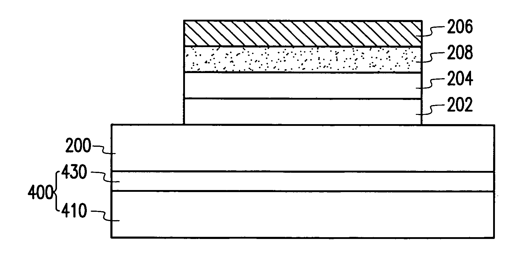
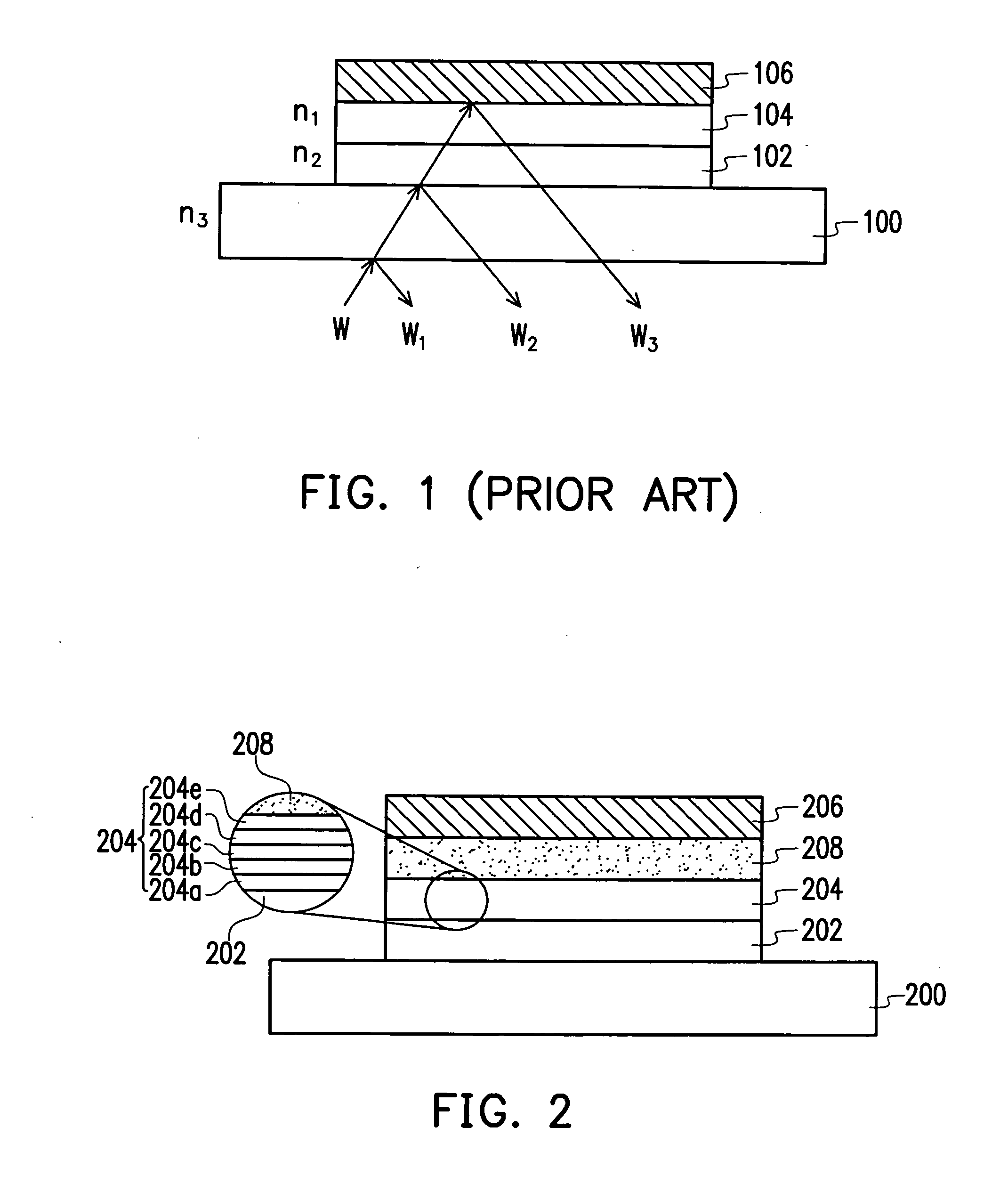
[0032] FIG. 2 is a drawing schematically illustrating an organic electroluminescence display device according to one embodiment of the present invention. Referring to FIG. 2, the organic electroluminescence display device comprises, for example but not limited to, a substrate 200, a first electrode layer 202, an organic functional layer 204, a second electrode layer 206 and an electrochromic medium layer 208. The substrate 200 comprises, for example but n...


PUM

PropertyMeasurementUnit
brightnessaaaaaaaaaa
transparentaaaaaaaaaa

Abstract

An organic electroluminescence display device is provided. The OEL device includes a substrate, a first electrode layer, a second electrode layer, an organic functional layer and at least one electrochromic medium layer. The first electrode layer is disposed on the substrate, the second electrode layer is disposed over the first electrode layer, and the organic functional layer and the electrochromic medium layer are disposed between the first electrode layer and the second electrode layer. Accordingly, the electrochromic medium layer is provided as a selective light valve to improve the reflection of the external light, and thus the contrast ratio of the organic electroluminescence display device is enhanced.

Description

[0001] This application claims the priority benefit of Taiwan application serial no. 92107664, filed on Mar. 31, 2003.[0002] 1. Field of the Invention[0003] The present invention generally relates to an organic electroluminescence (OEL) display device. More particularly, the present invention relates to organic electroluminescence display device having selective light valve.[0004] 2. Description of Related Art[0005] In recent years, communication appliance has become more and more important. Especially, portable communication appliance is the major stream of the communication appliance. In the development of the portable communication appliance, the flat panel display (FPD) used for the communication interface between the user and the appliance is important. The conventional flat panel display (FPD) may be generally classified into plasma display panel (PDP), liquid crystal display (LCD), inorganic electro-luminescent display, light emitting diode (LED), vacuum fluorescence display ...

Claims


Application Information

Patent Timeline
Patent Type & Authority Applications(United States)
IPC IPC(8): H01L51/00H01L51/30H01L51/52H05B33/00H05B33/12H05B33/22
CPCH01L51/0037H01L51/0077H01L51/5281H01L51/0084H01L51/0086H01L51/0078G02F1/157H10K85/1135H10K85/311H10K85/30H10K85/341H10K85/344H10K59/8791H10K50/86
Inventor CHANG, YIHLU, TIEN-RONG
Owner RITDISPLAY
Why Eureka
Try Eureka