Automatic pool cleaner gear change mechanism

a technology of automatic cleaning and gear change, which is applied in mechanical equipment, transportation and packaging, and gear changes, etc., can solve the problems of affecting the ability of the wall to scal

Inactive Publication Date: 2004-11-25
PENTAIR POOL PROD INC
View PDF38 Cites 14 Cited by
  • Summary
  • Abstract
  • Description
  • Claims
  • Application Information

AI Technical Summary

Benefits of technology

[0003] Accordingly it is an object of the present invention to provide an alternative cleaner and alternative mechanism for changing gears with which the applicant believes the aforementioned disadvantages may at least be alleviated.

Problems solved by technology

Known suction and pressure operated turbine driven cleaners for a floor and walls of a swimming pool suffer from the disadvantage that when they move through a sharp corner region between the floor and a wall, traction and suction are lost which impede their ability to scale the wall.
Furthermore, operation of gear change mechanisms on the known machines for causing the cleaner to change from movement in a first direction to movement in an opposite direction is, due to the complex nature of these mechanisms, not reliable enough, which results in damage to gears and even jamming and malfunctioning of the mechanisms.

Method used


Image

  • Automatic pool cleaner gear change mechanism
  • Automatic pool cleaner gear change mechanism
  • Automatic pool cleaner gear change mechanism

Examples


Embodiment Construction

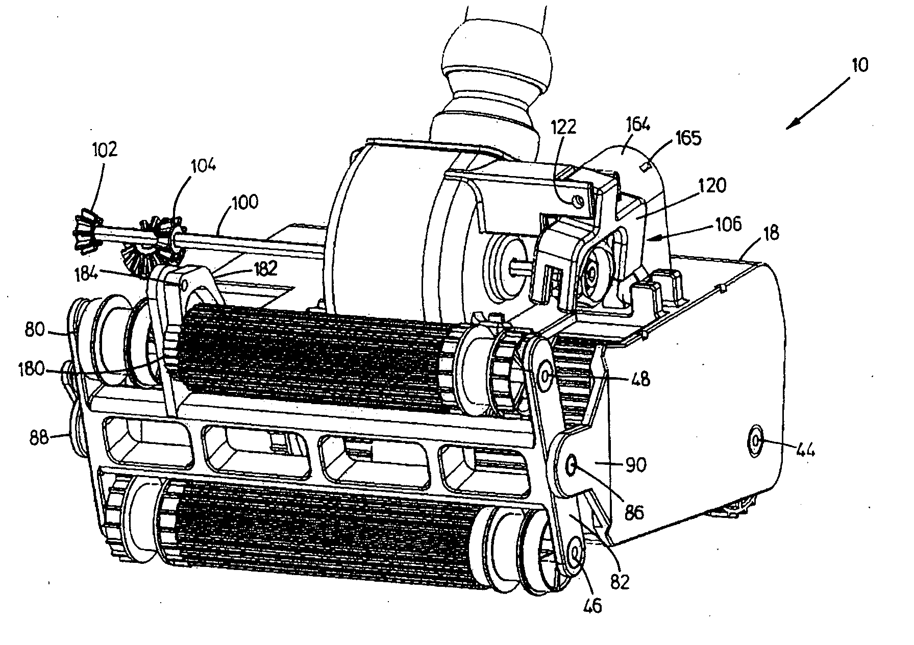
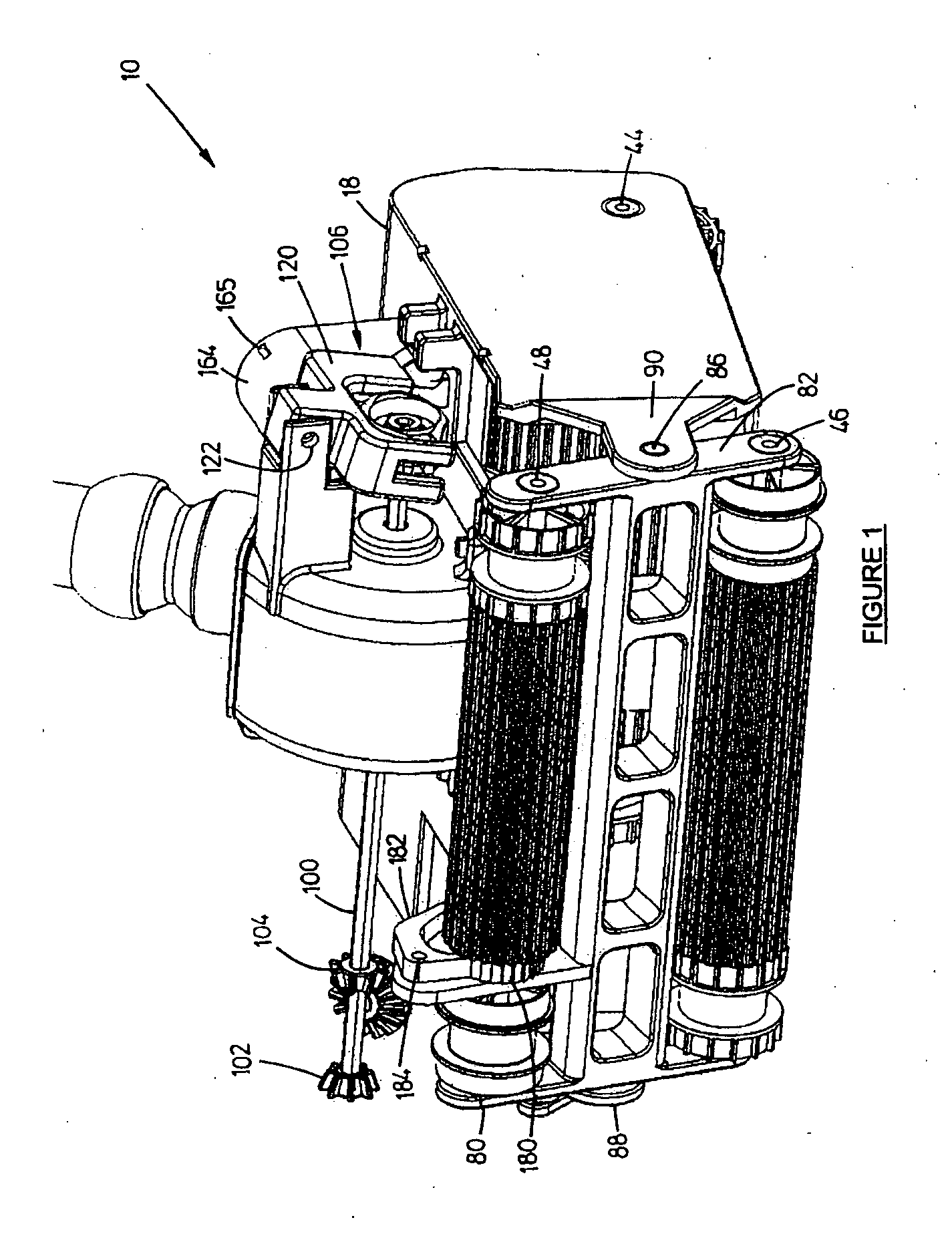
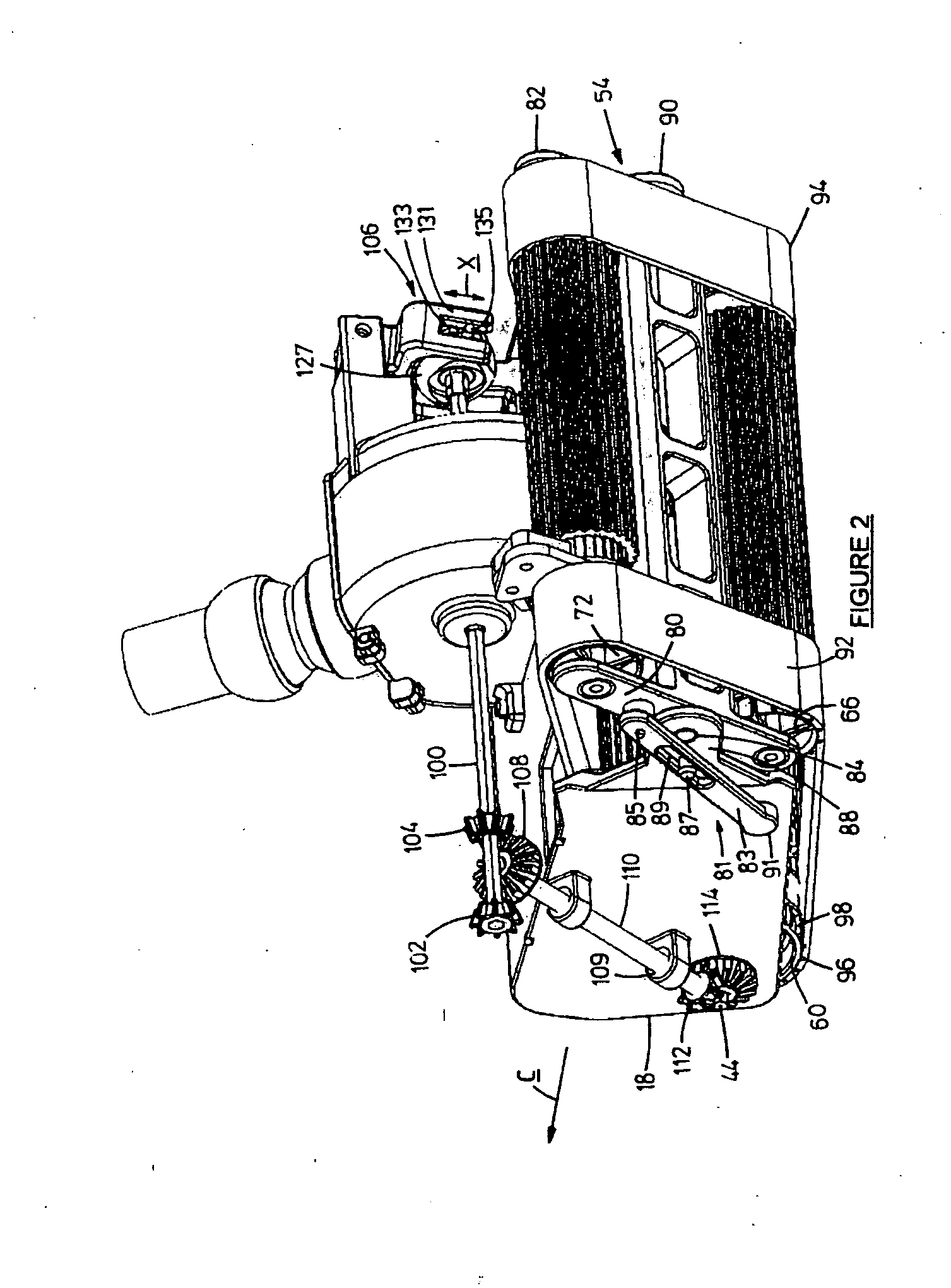
[0072] An automatic swimming pool cleaner according to the invention is generally designated by the reference numeral 10 in the diagrams. The cleaner is a turbine driven suction cleaner which in use, is connectable in known manner via a water intake (not shown) in a pool 12 (shown in FIGS. 14 to 16) to an inlet of an electrical circulation pump (not shown) of a circulation and filtration plant (also not shown) for the swimming pool 12.

[0073] The cleaner in use moves over a floor 14 and walls 16 of the pool and under the influence of the suction generated by the pump, sucks up water entraining debris and the like which is then filtered by the filtration plant, before the water is returned into the pool via suitably positioned outlets (not shown) into the pool.

[0074] The cleaner 10 comprises a body 18 defining a liquid flow passage 20 (shown in FIG. 4) therethrough. The flow passage 20 extends between an inlet 22 into the body 18 defined in a bottom plate 24 of the body and an outlet ...


PUM


Abstract

A mechanism (106) for selecting one of a first gear (102) and a second gear (104) for driving an automatic swimming pool cleaner 10 comprises a bi-stable oscillating gear change assembly 100. The assembly is moveable between a first position wherein the first gear is engaged and a second position wherein the second gear is engaged. A first magnet (142) is carried by the assembly. A second magnet (138, 140) is carried externally of the assembly on the cleaner body (18). A cam arrangement 152, 160 initiates movement of the assembly 100 from one of the first and second positions to enable mutually repelling forces between like poles of the first and second magnets (142, 138, 140) to cause the assembly to settle in another of the first position and the second positions, thereby to change between the first and second gears quickly and cleanly.

Description

[0001] THIS invention relates to automatic cleaners for surfaces submerged in a liquid and more particularly to such cleaners which are operated by a liquid driven turbine.[0002] Known suction and pressure operated turbine driven cleaners for a floor and walls of a swimming pool suffer from the disadvantage that when they move through a sharp corner region between the floor and a wall, traction and suction are lost which impede their ability to scale the wall. Furthermore, operation of gear change mechanisms on the known machines for causing the cleaner to change from movement in a first direction to movement in an opposite direction is, due to the complex nature of these mechanisms, not reliable enough, which results in damage to gears and even jamming and malfunctioning of the mechanisms.OBJECT OF THE INVENTION[0003] Accordingly it is an object of the present invention to provide an alternative cleaner and alternative mechanism for changing gears with which the applicant believes ...

Claims


Application Information

Patent Timeline
Patent Type & Authority Applications(United States)
IPC IPC(8): E04H4/16
CPCE04H4/1654Y10T74/19665F16H3/40
Inventor STOLTZ, HERMAN
Owner PENTAIR POOL PROD INC
Why Eureka
Try Eureka