Connector for an automatic pool cleaner

a technology for connecting cables and pools, applied in the direction of cleaning equipment, applications, pipe elements, etc., can solve the problems of devices getting stuck in corners or against stairs of swimming pools, and needing to be pulled out of corners

Inactive Publication Date: 2009-12-03
BALIE WAYNE BENJAMIN
View PDF20 Cites 0 Cited by
  • Summary
  • Abstract
  • Description
  • Claims
  • Application Information

AI Technical Summary

Problems solved by technology

However, these devices tend to get stuck in corners or against stairs of the swimming pool and need to be pulled out of the corners.

Method used


Image

  • Connector for an automatic pool cleaner
  • Connector for an automatic pool cleaner
  • Connector for an automatic pool cleaner

Examples


Embodiment Construction

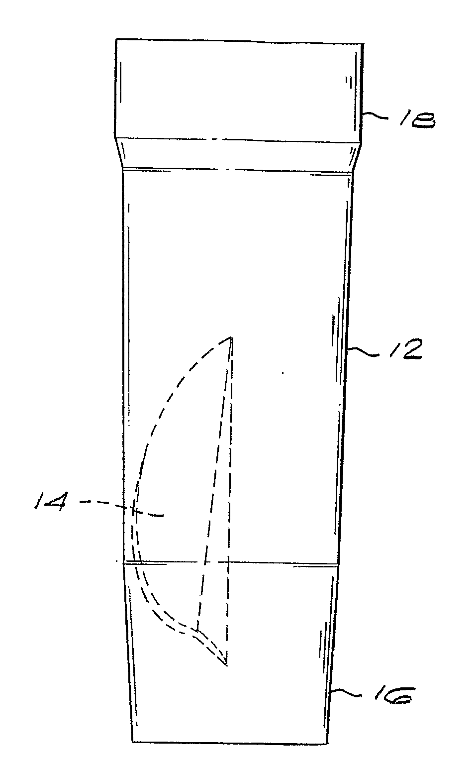
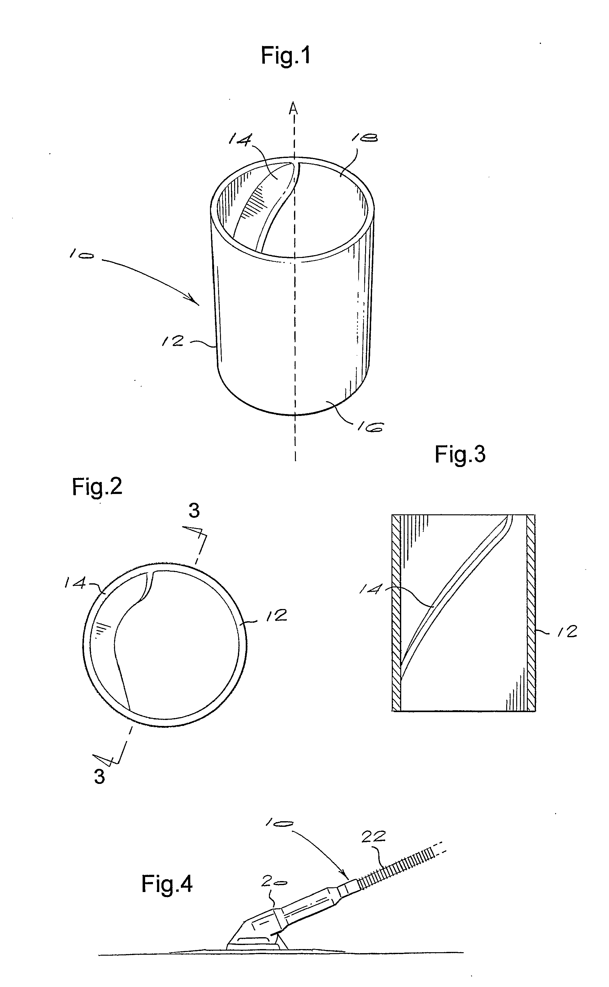
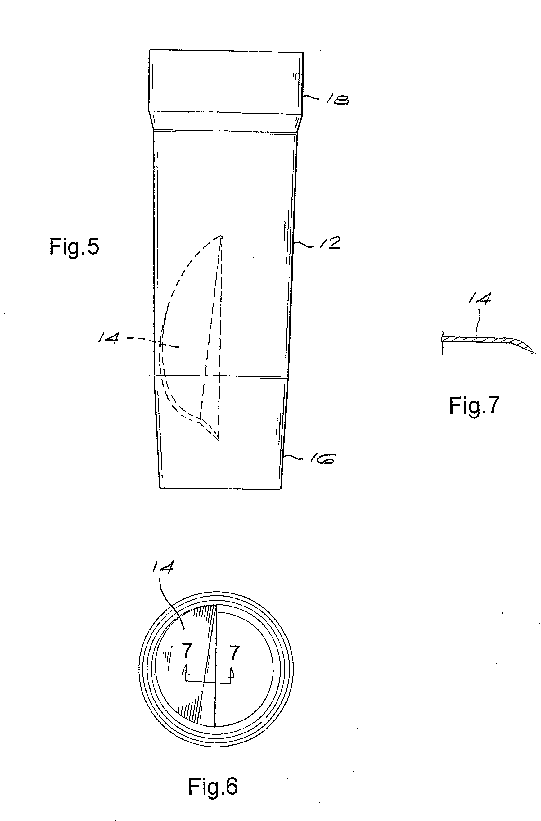
[0020]Referring to FIG. 1, a connector10 comprises a body 12 with a passage therethrough and a water deflecting member 14 located in the passage.

[0021]The water deflecting member 14 is arranged so that when water passes through the passage the water impacts on the water deflecting member causing the body to rotate around a longitudinal axis “A” of the body.

[0022]The water deflecting member 14 of the prototype took the form of a helix as illustrated in the accompanying drawings. However, it will be appreciated that the water deflecting member may take any one of a number of other forms.

[0023]A first connecting formation 16 is used to connect the body to an automatic pool cleaner 20 (FIG. 4) so that the body is able to rotate with respect to the automatic pool cleaner 20 and a second connecting formation 18 is used to connect the body to a pipe 22 (FIG. 4) used to connect the automatic pool cleaner to a filter system (not shown).

[0024]The first connecting formation is implemented by s...


PUM


Abstract

A connector for an automatic pool cleaner includes a body (12) with a passage therethrough and a water deflecting member (14) located in the passage. The water deflecting member is arranged so that when water passes through the passage the water impacts on the water deflecting member causing the body to rotate about a longitudinal axis of the body. The connector also includes first (16) and second (18) connecting formations for connecting the body between two pipes used to connect the automatic pool cleaner to a filter system or between one of the pipes and the automatic pool cleaner.

Description

BACKGROUND OF THE INVENTION[0001]This invention relates to a connector for an automatic pool cleaner.[0002]Automatic pool cleaners are devices which use the flow of water through them to move around the bottom of a swimming pool thereby cleaning dirt and debris off the bottom of the swimming pool.[0003]However, these devices tend to get stuck in corners or against stairs of the swimming pool and need to be pulled out of the corners.[0004]A number of devices exist which aim to prevent this from happening.[0005]The present invention seeks to implement an alternative device which prevents this from happening in an improved manner.SUMMARY OF THE INVENTION[0006]According to the present invention there is provided a connector for an automatic pool cleaner, the connector comprising:[0007]a body with a passage therethrough and a water deflecting member located in the passage, the water deflecting member being arranged so that when water passes through the passage the water impacts on the wa...

Claims


Application Information

Patent Timeline
Patent Type & Authority Applications(United States)
IPC IPC(8): F16L55/00
CPCE04H4/1663A47L9/242
Inventor BALIE, WAYNE BENJAMIN
Owner BALIE WAYNE BENJAMIN
Why Eureka
Try Eureka