System and method for operating a flow process

a flow process and flow technology, applied in the field of flow process system, can solve the problems of large number of flow process meters and burdening the central processor, and typical meters are invasiv

a flow process and flow technology, applied in the field of flow process system, can solve the problems of large number of flow process meters and burdening the central processor, and typical meters are invasiv

US20050005711A1Active Publication Date: 2005-01-13EXPRO METERS

Image

  • System and method for operating a flow process
  • System and method for operating a flow process
  • System and method for operating a flow process

Examples


Embodiment Construction

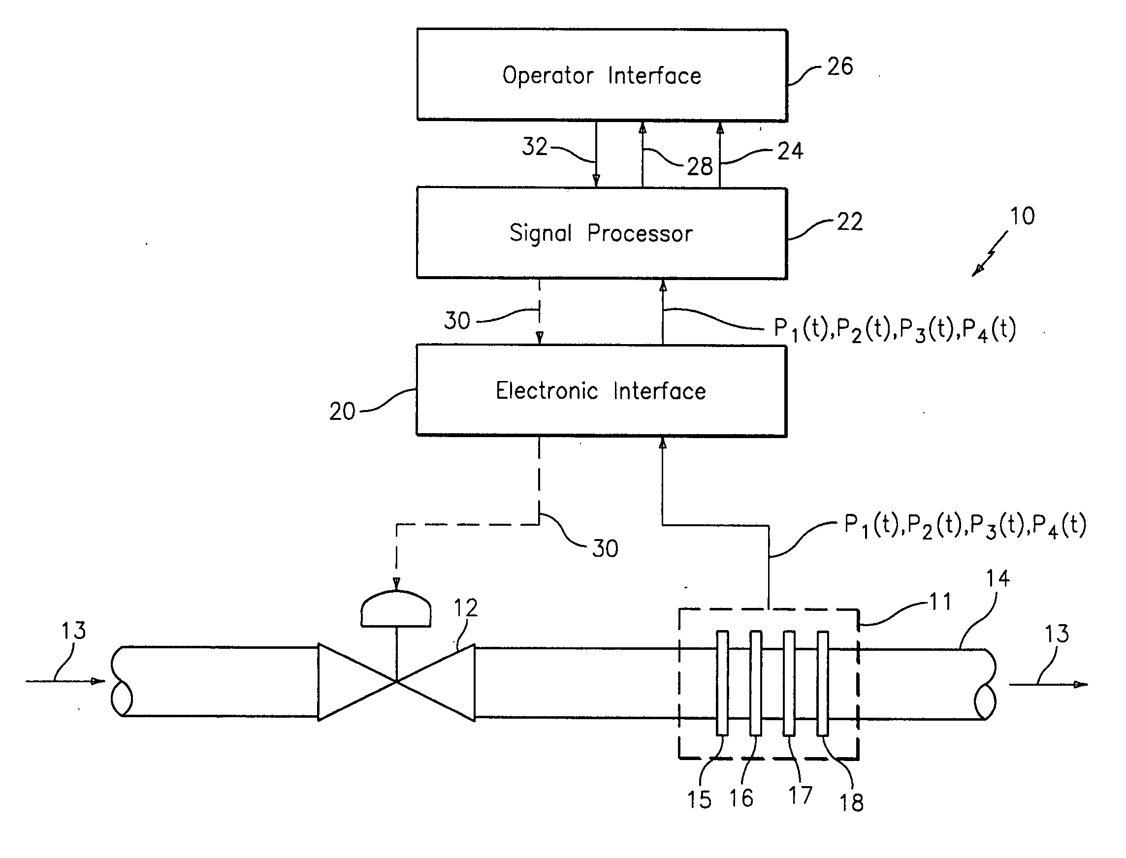
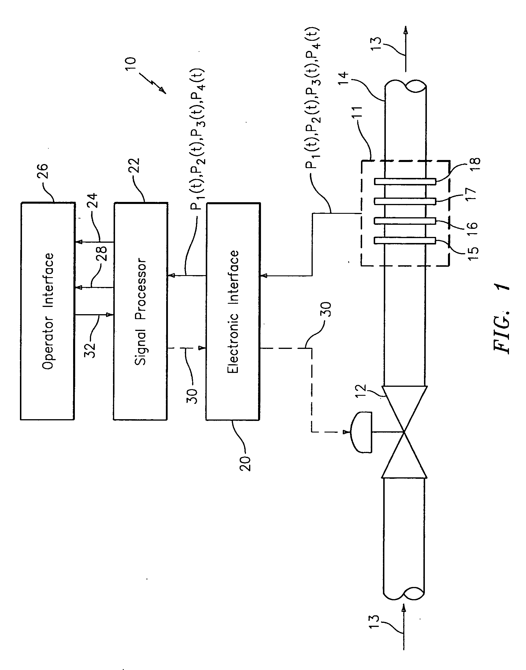
The present invention provides a distributed control system (DCS) architecture for monitoring a plurality of flow meters based on array-processing installed at various locations throughout a flow process, which is similar to that described in U.S. Provisional Patent Application 60 / 474,098 filed May 28, 2003, which is incorporated herein reference. The present invention further contemplates providing means to control the flow process and / or diagnose problems or anticipated problems with the flow process. The present invention is not limited to any particular industrial flow process. For example, the system embodying the present invention is applicable for the oil and gas industry, refining, food and beverage industry, chemical and petrochemical industry, pulp and paper industry, power generation, pharmaceutical industry, and water and wastewater treatment.

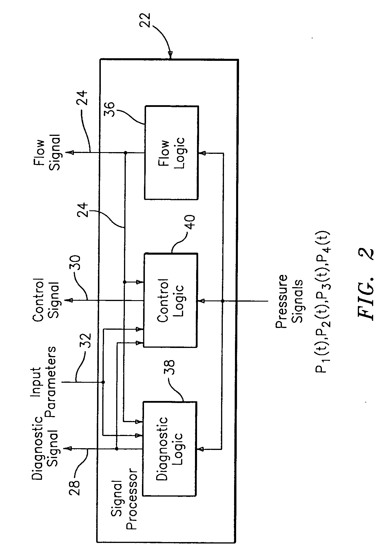
FIG. 1 illustrates a system 10 for operating a flow process. The term “operate” is considered to include the monitoring, diagnos...


PUM


Abstract

A system for monitoring, diagnosing, and / or controlling a flow process uses one or more flow meters based on an array of pressure sensors. A signal processor outputs at least one of a flow signal, a diagnostic signal, and a control signal in response to the pressure signals from the pressure sensors. The flow signal indicates the at least one parameter of the fluid, the diagnostic signal indicates a diagnostic condition of a device in the flow process, and the control signal is effective in adjusting an operating parameter of at least one device in the flow process. The system may be arranged as a distributed control system (DCS) architecture for monitoring a plurality of flow meters based on array-processing installed at various locations throughout a flow process.

Description

FIELD OF THE INVENTION This invention relates to a system for operating a flow process, and more particularly, to a system for monitoring, diagnosing, and / or controlling a flow process using one or more flow meters based on array-processing. BACKGROUND OF THE INVENTION A fluid flow process (flow process) includes any process that involves the flow of fluid through pipes, ducts, or other conduits, as well as through fluid control devices such as pumps, valves, orifices, heat exchangers, and the like. Flow processes are found in many different industries such as the oil and gas industry, refining, food and beverage industry, chemical and petrochemical industry, pulp and paper industry, power generation, pharmaceutical industry, and water and wastewater treatment industry. The fluid within the flow process may be a single phase fluid (e.g., gas, liquid or liquid / liquid mixture) and / or a multi-phase mixture (e.g. paper and pulp slurries or other solid / liquid mixtures). The multi-phase...

Claims


Application Information

Patent Timeline
13 Jan 2005
Publication
US20050005711A1
IPC
G01D4/00; G01F1/56; G01F1/7082; G01F1/712; G01F1/74; G01F7/00; G05D7/00; H04Q9/00
CPC
G01F1/363; G01F1/74; G01F1/7082; G01F1/662; G01F15/063
Inventors
GYSLING, DANIEL L.; KERSEY, ALAN D.